This thread has been locked.

If you have a related question, please click the "Ask a related question" button in the top right corner. The newly created question will be automatically linked to this question.

LMC6484: Instability when Op-Amp is off

Part Number: LMC6484
Other Parts Discussed in Thread: UCC28950,

Good morning.

I am using the LMC6484 and transistor MMBT2222ALT1 as a current source to sink current and change the voltage feedback on the UCC28950. The input for the + on the LMC6484 comes from a Digital to Analog Converter with a voltage range of 0V to 2V. Depending on the input voltage from the DAC, the feedback voltage will change and will make the output voltage on my converter change to my desired output. Please see a reduced schematic below.

Note: The DAC output is with respect to GND.

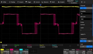
I am running into some problems when using the LMC6484 in this application, particularly when the input from the DAC is disconnected or 0V. This circuit shouldn't be doing anything when there is no input from the DAC, but it is causing a lot of jitter on my feedback voltage for the UCC28950. I have cut the trace that connects this part of the circuitry to the UCC28950 and there was no jitter after that, so I know it is related to the circuitry around the LMC6484. Module 1 seems to be almost immune to this jitter effect, probably because it is the module closest to where the LMC6484 circuitry lives and closest to GND. Module 2 is worse than Module 1, and Module 3 is the worst by far. Module 3 is the one furthest away from the circuitry around the LMC6484. 

When the DAC is 1V, and the circuitry is sinking current, there is still some noticeable jitter at the feedback of the UCC28950, but not nearly as bad as when the DAC input is disconnected or 0V.

Do you have any recommendations to mitigate this effect? 

Thank you for your time.

Alberto Miguez

  • I wanted to clarify that the reduced schematic that I presented above is incorrect. Q1, Q2, and Q3 connect to the UCC28950 feedback between the 2.1k and 22k resistors. Not between the 22k and the 2.8k. 

  • Hey Alberto, 

    I have a few questions to help me understand the issue a bit further?

    1. What is the supply voltage on the amplifiers U1B U1C and U1D?
    2. Can you provide a part number for the DAC so that I can understand how it interacts with the input of the amp?
    3. Have you tried doing an A/B swap with the amplifier from module 1 to module 2 or 3 and also put the amp from module 2 or 3 onto module 1 in order to determine if the issue follows the device or not? 
    4. What does the Jitter look like? An oscillation, noise etc? 
      1. Can you provide an Oscilloscope capture of module 1 vs module 3?

    Best Regards, 

    Chris Featherstone

  • Good morning.

    Sure, here are the answers to your questions:

    1. The supply voltage is 12V for U1. The designators U1A, U1B, U1C, and U1D are all part of the same chip. It is a quad op-amp, part number LMC6484AIM.

    2. DAC part number is TLV5638MDREP. The voltage signal that comes from the DAC looks clean when looking with the oscilloscope. The same signal is shared to all 3 modules.

    3. I have tried with two different boards (built with same part numbers but not reusing the parts from previous board) and the problem is the same where BUS1 looks good, but BUS 2 and 3 look very jittery.

    4. It appears to me as a jitter when looking at the H-bridge on the UCC28950 circuit. See comparison of Module 1 vs Module 3. Please note that when I remove the sinking current circuitry, Module 3 goes back to normal to look like Module 1. Output voltage with either module is steady at 24V. I am just concerned with the amount of jitter I see on Module 3, not its actual performance. 

    Figure 1: Module 1 H-bridge of Phase-Shifted Full-Bridge with UCC28950 controller

    Figure 2: Module 3 H-bridge of Phase-Shifted Full-Bridge with UCC28950 controller

  • Hey Alberto, 

    I had one more question. Was this jitter occurring when the op amp is turned off? I saw in the title of the post that the issue occurs when the op amp is turned off. By turned off do you mean that the power supply to the amplifiers is 0 V?

    Best Regards, 

    Chris Featherstone

  • Hello again Chris,

    Sorry for the confusion. The jitter occurs when the op amp is on (VCC_ISO is 12V), but the input from the DAC is 0V or disconnected going into the + of the op amp. 

    Please let me know if you have any other questions.

    Thanks,

    Alberto Miguez

  • Hey Alberto, 

    Thank you for the clarification. I have put the circuit into tina ti in order to better understand the issue and analyze the problem. I am currently simulating the circuit to see if I can identify any issues. I attached the Tina simulation to the bottom of the post as well. If you see any adjustments that are needed to better align with your setup let me know and I can modify the circuit.

    3286.LMC6484.TSC

    Best Regards, 

    Chris Featherstone

  • Thank you Chris.

    For my latest configuration, R13 should be changed to 552 ohms so the node between the 22k and the 2.8k is regulated to be 2.5V by the UCC28950 at 28V.

    I have tried using different combinations of DAC voltages and resistors on the R13 location to see if it would make a difference, but it didn't.

    Beyond that, the simulation looks mostly accurate to what I have but I believe C2 doesn't exist on my circuit.

    The circuit itself appears to work just fine when used on Module 1, but causes a lot of jitter on Modules 2 and 3. I am not sure if layout and having far longer paths between the sinking current circuit and the feedback network on the UCC28950 has an effect. 

    Please let me know if you find something.

    Thank you,

    Alberto Miguez

  • Hey Alberto, 

    What pins are the two measurements below made on? I see part of the waveform goes negative. I think the ringing on the good module is from the scope probe needing to be calibrated? I do wonder if you may be seeing some crosstalk that is creating the jitter on the other screen capture. Is there a way you can isolate module 3 by lifting the input pins on module 1 and 2 or some other method? 

    Best Regards, 

    Chris Featherstone