This thread has been locked.

If you have a related question, please click the "Ask a related question" button in the top right corner. The newly created question will be automatically linked to this question.

OPA569: Current monitor output shows non-linearity when output is near positive rail.

Part Number: OPA569
Other Parts Discussed in Thread: OPA596,

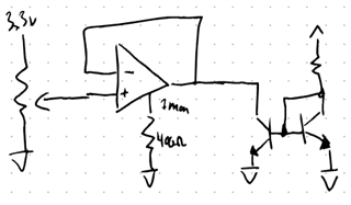
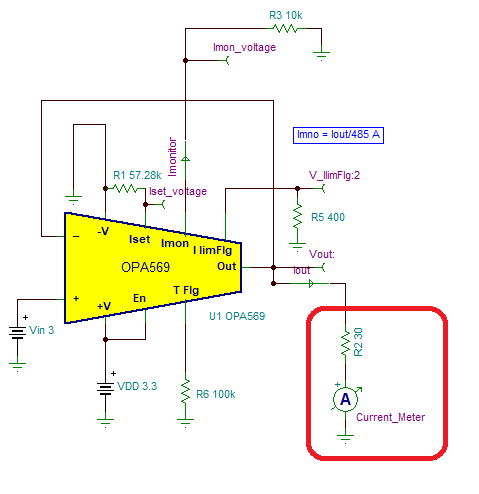
I’m driving a laser diode with this opamp (single supply) and monitoring it using the Imonitor pin with a 400ohm pull-down to ground. 

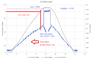
I’m aiming for a 95mA output which requires just over 3V with my specific laser and associated series resistors. I’m powering the opamp off 3.3V. 

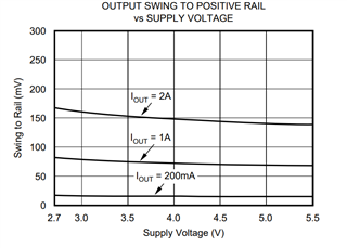
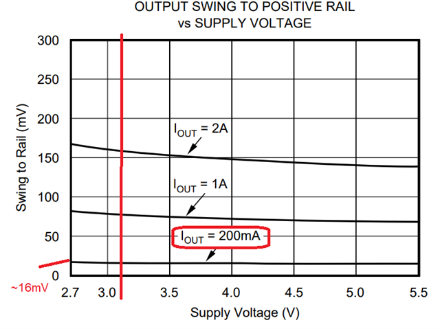
This isn’t a problem for the output swing since the data sheet indicates a swing to within ~25mV of the positive power rail. 

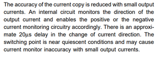
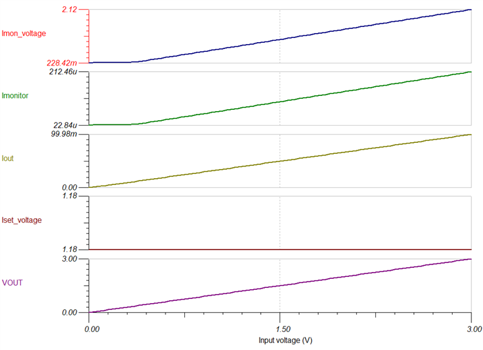
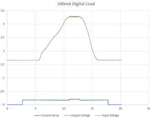
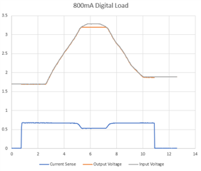
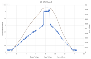
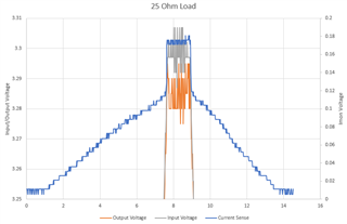
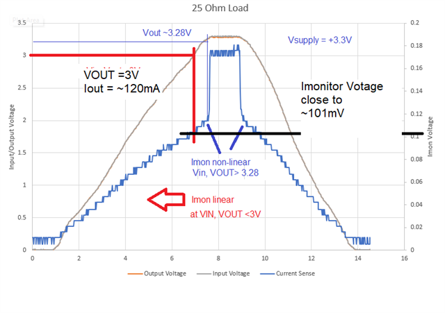
The issue is with the Imonitor pin. As the output voltage approaches 3V, there is no longer a linear relationship between Imonitor’s output and the actual output current. 

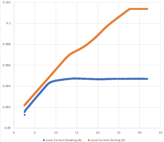
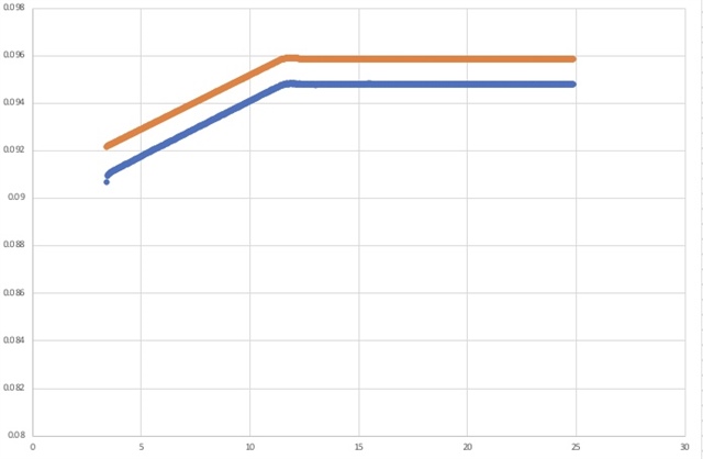
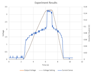
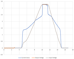
In this plot “laser current reading” is current measured by another device. “Laser current setting” is the current as reported by IMonitor. Both converted to amperes with the appropriate math. I assume the small offset at the start is due to component tolerances.

Is there any documentation on nonlinearity of the Imonitor pin with output voltages approaching the power rails? The only plots I found were regarding output current or temperature. 

  • And to add, if I short one of the series resistors, the driving voltage drops to around 2.7V, and Imonitor pin has a more linear response. 

  • The datasheet says:

    Additionally, the swing on the IMONITOR pin is smaller than the output swing. When the amplifier is sourcing current, the voltage of the Current Monitor pin must be at least two hundred millivolts less than the output voltage of the amplifier. Conversely, when the amplifier is sinking current, the voltage of the Current Monitor pin must be at least two hundred millivolts greater than the output voltage of the amplifier. Resistive loads are able to meet these restrictions. Other types of loads may cause invalid current monitor values.

    A simple way to monitor the load current and meet these requirements is to connect a resistor (with resistance less than 400 • RL) from the IMONITOR pin to the same potential to which the other side of the load is connected. Another method is to use a transimpedance amplifier, as shown in Figure 4. This circuit must assure that the potential of the IMONITOR pin remains in the valid voltage range by connecting it to the same potential to which the load is connected—most likely ground for dual supply or mid-supply for single-supply applications.

  • I have 400ohms from Imonitor to ground. Imonitor is around 70-80mV while the output is 3V. I don’t think that’s my issue. 

  • Hi Michael,

    As you have mentioned, the Imonitor pin must be at least 200mV below the output while is sourcing current.  It would appear that you are meeting the spec based on your text description, but we would like to review the circuit.

    1) Also, the voltage on the current limit pin Iset tolerance has a restricted voltage range as well. What is the resistor value on the Iset pin?  Is there a voltage applied in series with the resistor on the current limit set pin?

    2) Can you please provide the OPA569 complete schematic, including feedback components, Iset, Imon and I lim flag connections, supply connections and bypass capacitors?  If possible, please include the the laser diode and or load circuit connected at the OPA569 output.  Let me know if there is any other load connected to the output of the OPA596.

    The current monitor is  accurate to ±3% typical (±10% max) of Io=1A current, where the % tolerance on the current monitor is given by:

    % Tolerance = [(Iout/475)  - Imonitor]*100 / Imonitor 

    However, keep in mind, the datasheet Imon description mentions the accuracy of the current copy is reduced with small output currents.

    Thank you and Regards,

    Luis   

  • Hi Luis,

    Thanks for the response.  To clarify, this isn't my design; I'm trying to figure out what is wrong with someone else's design.  The end solution is likely to be "use a different opamp," but I'm trying to figure out if it's the only thing wrong with this circuit.

    1) The Iset resistor is 100k which should correspond to 115mA. I've tested, and this works though the actual limit varies depending on the resistance of the load. The limit seems to shrink as resistance rises/current drops.  This is interesting, but I don't think it's the primary issue I'm dealing with.  As you've mentioned, it's inaccurate at light loads.

    2) Unfortunately, I cannot provide that information (proprietary), but I was able to perform an experiment that isolates the opamp and I think better illustrates the behavior I've noticed.  I set up the opamp as a simple voltage follower driving a BJT current mirror set at around 100mA.  Everything is powered by a 3.3V supply, and the input is connected to a potentiometer that I can turn to sweep from 0V to 3.3V input.  Below you can see the behavior of the Imonitor pin as the input (and output) voltages are changed.

    As you can see, input and output voltages track perfectly. This is expected as the 100mA load should allow the output to swing very close to the rails.  Also, the Imonitor pin reflects the relatively flat current draw of the current mirror.  However, when the input/output voltages get very close to the 3.3V rail, Imonitor shoots up dramatically by roughly 50%.

    I'm aware that the current monitor accuracy can vary due to temperature, load, and supply voltage, but I see no mention on the datasheet of behavior changes due to the output voltage.

    What can explain this behavior?

  • HI Michael,

    Please note that the current limit can be set in the range of ±0.2A to ±2A, so 115mA is outside of spec.

    Setting the current limit to 200mA, with Rlimit=57k, TINA simulation provides the expected result, when Vout = 3V.  I used a ~30Ω load for simulation purposes, the amplifier is sourcing about ~100mA while Vout =3V.


      I set up the opamp as a simple voltage follower driving a BJT current mirror set at around 100mA.  Everything is powered by a 3.3V supply, and the input is connected to a potentiometer that I can turn to sweep from 0V to 3.3V input

    It is a little difficult to comment without an schematic.  I did not quite follow this comment,  what do you mean the amplifier is driving a BJT current mirror?  Is the output of the OPA569 sourcing 100mA in to a laser diode in this case?

    Thank you and Regards,

    Luis

  • Hi Luis,

    In my experiment, I have removed all connection between the opamp and the laser.  Here's a quick doodle:

    I have the resistor in the current mirror configured to draw around 100mA of current.

    With this circuit, I would expect the voltage on Imonitor (and the output current) to be relatively constant over the input/output voltage range (because of the current mirror).  In the plot in my previous post, you can see the Imonitor voltage slowly rise to 90mV. It's not a perfect current mirror, but you can see how the current stays relatively flat compared to the voltage.  With 400ohm load on Imonitor, 90mV corresponds to 106mA.

    But then suddenly as the output voltage gets very close to 3.3V, the Imonitor pin shoots up to 150mV (179mA).  The actual current is not changing by this much. It appears the IMonitor pin is not functioning correctly at this output voltage.

  • Hi Michael,

    Looking carefully at the simulation of my previous post, it actually shows the Imonitor is not quite accurate down to this low level current output current of ~100mA while using the small 400Ω resistor referred to GND (V- supply), with unipolar supply. The issue may be that the Imonitor voltage is too close to the negative supply when using the small Imon resistor.

    The Imonitor voltage is more restricted than the output swing of the Op-amp. When powering with unipolar supply, where V- =GND, the Imon voltage requires headroom well above >~200mV above/and below the OPA569 minimum output swing.

    In this case in your data, the limitation Imonitor is limited to 169mV (or less) above (V-); which is outside the linear region. 

    In simulation, if we increase the Imonitor resistor to ~10k , the Imonitor voltage stays more than +220mV above the negative supply (for most of the range, for output currents well above ~11mA), and the Imonitor voltage stays well below the maximum Imonitor voltage of 3.3V - ~0.250V = ~3V. The simulation still shows that the result is not quite accurate at the very low currents, but it is in the linear region when the output current is above >11mA. 

    1) Can you please change the I monitor resistor to ~10kΩ, and see if your test results improve? See simulation with a 10kΩ resistor on Imon below.  Imon=~212uA which corresponds to 100.9mA, close to the 99.98mA current output.  See simulation below.

    2) Another experiment will be to power the OPA569 with bipolar supplies, with (V-) slightly negative. For example set (V-) more negative than <~-300mV, should place the Imon inside its linear region. 


    Thank you and Regards,

    Luis

  • Hi Luis,

    I was able to change the Imon resistor to 10k, but I got similar results.

    While taking this measurement, I also determined that the behavior appears to depend entirely on the output voltage.  As my current mirror heated up, it started passing more current which triggered the current limit setting of the opamp very slightly dropping the output voltage.  You can see what happened here:

    Only when the output voltage is very close to 3.3V does this issue occur.

    I discovered something new while capturing this data. I returned to the 400ohm IMonitor resistor, bumped the current limit up, and tried using my digital load (I used the current mirror originally because my load only goes down to 200mA).

    With 200mA load:

    And 800mA load:

    As expected, the output voltage swing is reduced with the increased load, but unexpectedly, the IMonitor voltage behaves oddly when this swing limit is reached. In the second example, it actually drops as the input surpasses the output swing bounds.

    I believe this could explain what has been going on. Even with the original light 100mA load, the output voltage still needs to get very close to 3.3V to produce the result, and it could be bumping into the swing limit for that load.

    Are you able to reproduce this in your simulation or provide any explanation? There doesn't appear to be any note on the datasheet that links IMonitor accuracy to output swing.

  • Hi Michael,

    - There is no schematic available or component description of the current test circuit/current mirror, therefore it is hard to debug or comment on the current mirror test setup.  Please perform a direct current measurement at the OPA569 output  using a current meter connected in series between the OPA569 output and the load circuit, to confirm that ~100mA are sourced at the op-amp output when the issue occurs.

    - A simple test circuit will be to connect a load resistor 30Ω, 0.5W (>0.3W) at the OPA569 to ground, and plot the Imon voltage vs OPA569 input voltage.  You can also connect a current meter in series with the 30Ω resistor to monitor current.

    The OPA569 output voltage swing spec is around ~20mV from the positive rail while supporting ~200mA load, so the amplifier output swing is not a problem while powered with 3.3V supply and loaded with 100mA, with the output set to 3V. 


    Best Regards,

    Luis  

  • Hi Luis,

    I hope you had a nice holiday.

    Below is a trace of the opamp driving a 25ohm load. I don't have a current meter, but you can easily calculate the max current across the load as 3.3V/25ohm = 132mA.

    As you can see, the same behavior occurs. Furthermore, when you zoom in, you can see that the odd IMonitor behavior specifically occurs when the output voltage is not able to swing as far as the input voltage:

  • Hi Michael,

    Hope you had a good weekend as well.

    The plots on the last post, where the op-amp driving a 25ohm load directly, show the expected behavior. 

    The current sense waveform looks linear until the OPA569 output is right at about +3.285V (~about 15mV from the rail), where the OPA569 the device output swing approaches the output swing limitation, with no headroom from the +3.3V positive rail supply.

    The expected OPA569 typical output voltage swing spec requires more than ~20mV from the positive rail while supporting ~200mA load, so the amplifier output swing is not a problem while powered with a +3.3V supply and loaded with 100mA, with the output set to 3V.  The plot shows the Imonitor is linear for input, output voltages at +3V, and below 3V driving up to 120mA; and the circuit only shows issues when the output is above 3.28V, where the device output swing is out of range.

    As we discussed, the IMON is specified at an output current of 1A to ±10%, hence, it is not expected to be accurate at the very low output currents, where current output is small. The datasheet Imon description mentions the accuracy of the current copy is reduced with small output currents.

    Thank you and Regards,

    Luis

  • Hi Luis,

    Thank you for the quick response, but I'm still not 100% satisfied.  The lack of headroom fully explains the output not matching the input under load, and I understand that IMon is specified as 10% at 1A, but I still don't have a satisfying explanation for *why* this nonlinearity appears exactly where it does.  The signal is close to 0% error until it suddenly jumps to over 50% error.

    I don't see any mention in the datasheet of a connection between the output swing limit and Imonitor linearity.  If the answer is simply "the opamp behaves weird when driven past its rated output swing," I will accept that. I was just hoping there was a specific line I could point to on the datasheet to explain this relationship.

    The only warning about IMon voltage relates to headroom between the output voltage. IMonitor voltage must be at least 200mV less than the output voltage. But in my case, it's over 3V.

  • Hi Michael,

    The OPA569 functions as other typical rail-to-rail output operational amplifiers in the market; where the Op-amp output output can swing close to the rail, but can not quite reach the supply rail. This is not unique to the OPA569 but it is consistent with many rail-to-rail output operational amplifiers in the industry.  Please see the output swing to positive rail vs supply voltage.  

    Please note, in the output condition on the plot above, the op-amp output is already slammed against the rail, hence the output stage is saturated and well-outside its linear region. If you need to operate at input/output signals at +3.3V, you will need to power the amplifier with a supply larger than 3.3V.  If you need to source ~125mA, I would recommend to allow a conservative headroom, at least +100mV of headroom from the positive for output swing.

    The current monitor is an analog circuit, and it is part of the op-amp output stage, where the current sense circuit consists of a internal circuit sensing the current creating a 1:475 copy of the output current. This monitor circuit is connected / biased as part of to the output stage of the OPA569.  In this case, because the output stage of the op-amp is slammed against the rail and saturated, where the output stage is operated well outside the specified linear region, the current sense circuit does not work linearly, since the internal circuitry is no longer biased properly. Hence, both the op-amp output and the current sense pin must operate within their output swing specifications.  

    On the data on your plot, assuming you are using a 400Ω resistor on Imon, and 25Ω load at the amplifier output, the Imonitor output provides the correct reading: At Vout=+3V, with 25Ω load, Iout = +3V / 25Ω = 120mA.  Imonitor makes a 1:475 copy of the output current, or Imon = ~252µA.  If you use 400Ω Imonitor resistor, this corresponds to 400Ω*252µA ~101mV.  This calculation agrees with your plot.

    Below is a TI Precision Labs Tutorial that discusses input/output limitations of operational amplifiers for a detailed explanation or rail-to-rail output amplifiers.  

    Input and output limitations - Output swing

    On the original post mentions the applications requires to source a 95mA current output with a voltage just over 3V to drive the laser, while powering the op-amp with a +3.3V supply. The circuit will operate properly as long as the output has headroom (allow a 100mV conservative headroom) from the supply. However, if you need to drive the output of the amplifier output very close +3.3V, then unavoidably, you will need to increase the power supply to >~ 3.4V as you will reach the output swing limitation, and the amplifier and its circuitry will be outside the linear operative region.   

    Thank you and Regards,

    Luis


  • Hi Luis,

    Thank you for the thorough response.  You have answered all of my questions.

    Regards,

    ~Michael