This thread has been locked.
If you have a related question, please click the "Ask a related question" button in the top right corner. The newly created question will be automatically linked to this question.
I plan to use AMC1200 and a shunt resistor to sense PV current. I have 5V independent voltage regulator for powering AMC1200 on VDD1 and GND1 pin and other isolated 5V regulator for VDD2 and GND2. The PV's negative rail is connected with GND1 of AMC1200. Is it okay to use the high side mode to measure the current?
The basic schematic looks like this:
I+ is from PV positive rail
I- is going to positive rail of buck converter
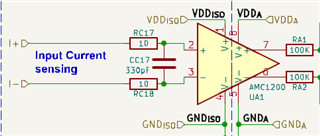
I+ and I- connected to 5mR R-sense
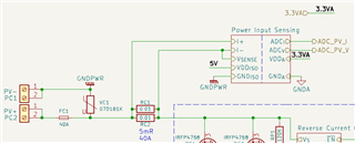
Thank you,
Arham
Hi Arham,
This will likely not be OK. Please refer to maximum input voltage limits with respect to GND1 as shown in the datasheet.
Design considerations for isolated current sensing from this FAQ may help: https://e2e.ti.com/support/amplifiers-group/amplifiers/f/amplifiers-forum/1164993/faq-isolated-data-converter-collateral-overview
Hi Alexander, I forgot to inform you that I+ and I- are connected to 5mR R-sense. The maximum current through this R-sense is about 40A.
I just attached the picture at the main post
Hi Arham,
What is the voltage potential between PV+ and PV-?
The inputs voltage potential will be much higher than GND1 if performing high side current sensing. I recommend connecting GND1 to PV+ to ensure the inputs remain within the input voltage common-mode range.
If design of the high side supply does not allow this, I recommend considering the AMC3301 or AMC3302 devices with integrated DC/DC converters.
The voltage between the PV+ and PV- is 150V, if I separate/isolate the PV- and GND1 is it will be fine?
Hi Khyarul,
No, as the input and high side GND1 need to be referred to the same voltage.