This thread has been locked.

If you have a related question, please click the "Ask a related question" button in the top right corner. The newly created question will be automatically linked to this question.

AMC1200-Q1: AMC1200 -Q1

Part Number: AMC1200-Q1
Other Parts Discussed in Thread: AMC1200, AMC3301, AMC1300

Dear support,

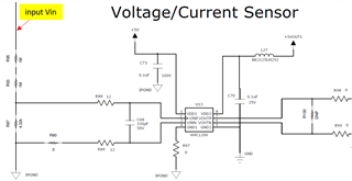
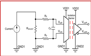
I use AMC1200 to do current sensing in my design.

The input power of my design is DC 48V to 160V.

VDD1 & VDD2 = 5V, magnitude of current to measured =0.68A

But when i power up my circuit with 48V input, Rshunt= 350m Ohm burn.

1.Is it the current flow through the Rshunt too high?

  So i should add R93, R95, R86 & R90 resistor to limit the current flow through the Rshunt .

2.Please help to confirm my circuit design is correct or not?

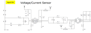
  I refer to below schematic for my design.

Here i attached my schematic for your reference.

SCH-1096-00_Current Sensing.pdf

Thank you.

Regards,

Ku

  • Dear Support,

    I modify my schematic design by not insert the R91 resistor and supply different Vdc to confirm the AMC1200 Vout.

    I found out that the output look like not much different. 

    Is that my schematic design wrong or component value wrong?

    Here the data i took based on measurement took on PCBA.

    Input Voltage at J12 Point A Point B VDD1 VINP VINN VDD2 VOUTP VOUTN
    47V 45.45V 45.32V 3.51V 4.174V 4.176V 5.11V 2.473V 2.572V
    52.1V 50.01V 49.9V 3.771V 4.462V 4.514V 5.1V 2.505V 2.519V
    57.2V 55.02V 54.95V 4.128V 4.836V 4.848V 5.09V 2.4769V 2.5208V
    62.2V 60V 59.99V 4.427V 5.072V 5.086V 5.11V 2.502V 2.497V

    SCH-1096-00_Current Sensing A.pdf

    AMC1200 current sensing waveform.xls

    Best regards,

    Ku

  • Hi Ku,

    The input voltage VINP and VINN are higher than VDD1. The device cannot measure voltages greater than VDD1. 

    I recommend replacing AMC1200 with AMC3301, a device with internal DC/DC converter. 

  • Hi Smith,

    Now i had modified my design based on Isolated Amplifier Voltage Sensing Calculator.

    Because the calculator table no AMC1200 ,so i use AMC1300 as reference.

    So below is my latest schematic design for voltage sensing circuit,

    Attached my measured data with Vin =40V to 124V.

    Vin (V) VINP(mV) VINN(mV) VOUT (differential)
    40V 46.57 -8.19 369.1mV
    45V 53.38 -4.57 428.2mV
    50V 62.06 -2.95 479.6mV
    55V 69.12 -1.33 528.1mV
    60V 80.33 0.78 585.7mV
    124V 159.84 12.99 1.121V

    Please help to confirm is my design now is correct?

    AMC1200 Voltage Sensing waveform.xls

    Thank you .

    Best regards,

    Ku

  • Hi Ku,

    The R3' resistor should not be necessary for the AMC1200. The front end design of the AMC1200 and AMC1300 are different, the AMC1300 has a static input bias current that influences the measurement for voltage sensing. 

    The results do look much better than before however. 

  • Hi Smith, 

    so the schematic of AMC1200 for voltage sensing will be as below,

    If i want to calculate the Vout differential of AMC1200, is the equation as below correct?

    [(R87/R93+R95+R87) x Vin] x 8, nominal gain of AMC1200

    I want to see how much accurate my actual measurement data compare to calculation data.

    Thank you very much.

    Best regards,

    Ku

  • Yes, however you may need to consider that the input impedance, as shown in Figure 31. Equivalent Input Circuit, is in parallel with the sensing resistor R87. This will lower the equivalent sensing resistance.