This thread has been locked.

If you have a related question, please click the "Ask a related question" button in the top right corner. The newly created question will be automatically linked to this question.

OPA462: Techniques for Extending the Usable Power Supply Range of the OPA462 High-Voltage Op Amp

Part Number: OPA462
Other Parts Discussed in Thread: TIDA-060033, THS3491, , LMC662

Dear Team,

Question:1

I was reading the application note and I understood the design.

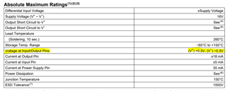
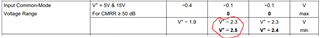
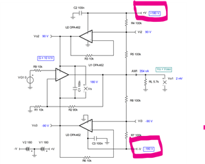
But my question is how do we calculate or decide the value of V+ and V- as shown below.

I also read this design note "Design Guide: TIDA-060033 Bootstrap High-Output Voltage-Extension Reference Design ".

In all these application note  V+ and V- is taken as granted.

May I know how to select value of V+ and V- .Is there any thumb rule exists.

Question 2:

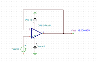
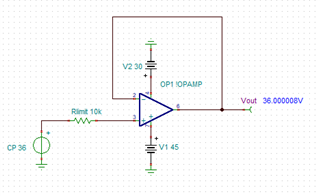
I am also designing a circuit similar to it. My input voltage varies from 35V to 37V.

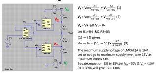
I also assumed the value of V+ and V-. My design calculations are given below. May I know your comments

Regards

HARI

  • Hi Hari,

    Both the OPA462 application note and the THS3491 reference design show the maximum extendable range of the power supply using the bootstrapping technique. Notice that both designs use the maximum single power supply voltage for the bootstrapping amplifiers U2 and U3. That is 180V for the OPA462 and 32V for the THS3491. The power supply for a single amplifier cannot exceed this maximum supply voltage, however the bootstrapping technique allows the power supply of U1 to be effectively doubled to +/-180V (360V) and +/-32V (64V).

    Can you provide more information about your application and what you are trying to accomplish? It appears that your signal amplifier is configured as a buffer with an input signal from 35V-37V. This means that your output swing is only 2Vppk. The purpose of the 3-amp bootstrapping circuit is to increase the output swing of the signal amplifier to ranges that exceed the maximum supply voltage of the amp. In the bootstrapping configuration, the power supplies of the signal amplifier move up and down in response to the output voltage in order to allow this.

    As your desired output swing is only 2Vppk, you can achieve this smaller output swing by simply offsetting the power supply rails to fixed values that will accommodate your 35V-37V input and output range and satisfy the operating limit: (Vcc) - (Vee) <= 15V.

    For example, you can achieve this with fixed supplies of Vcc = 45V and Vee = 30V where Vcc-Vee = 45V-30V = 15V

    Regards,

    Zach

  • Hi Zach,

    My input to the buffer is coming from a charge pump.

    Charge pump output voltage varies from 35V DC to 37V DC maximum.

    The buffers maximum input voltage is 16V.That is why I went to bootstrapping.

    Regards

    HARI

  • Hi Hari,

    The valid input and output range of the LMC662 (or any amplifier) is determined by the exact value of the power supply voltages. See the absolute maximum rating is given relative to the supply voltages V+ and V-.

    The valid common-mode input range and output swing are also relative to the supply voltages. 

    As long as V+ - V- is equal to 15V, we can apply these specifications to any power supply voltages, for example the 45V and 30V supplies I suggested previously. In fact, the entire bootstrapping method is based on this principle. As the output voltage moves up and down, the bootstrapping amplifiers shift both supply voltages up and down to ensure the input and output signal remain within the valid power supply range.

    In your case, you do not actually require the power supply voltages to move with the output signal because your output swing is only 2Vppk. As long as your power supplies are set to accommodate a 35V-37V input and output signal, these power supply voltages may remain fixed.

    One other thing to consider is that depending on the power supply sequence, it is possible that you may violate the abs max and damage the amplifier. This can occur in the case that the charge pump voltage rises before the LMC662 power supply, or if the LMC662 supply rises first while the charge pump output is still low. To prevent the device from being damaged, I recommend including a current-limiting resistor of at least 10kΩ at the non-inverting input pin of the LMC662.

    Regards,

    Zach