Other Parts Discussed in Thread: INA283
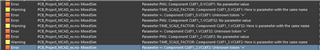
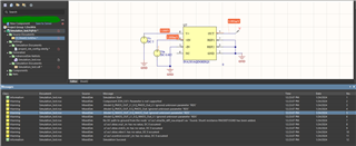
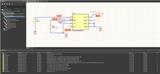
I am using the PSpice sim model from the TI web design resources in Altium and get the following error messages (attached pic). Could you help resolve the errors?
Original question:

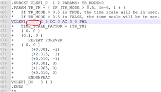
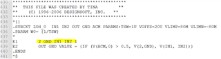
TINA/Spice/INA286: ERROR(ORPSIM-16352): Time value must not be an expression