Other Parts Discussed in Thread: TINA-TI
Hi Expert,
Issue: Common mode voltage has wrong gain when debug the circuit in my system. Why?
Schematic:
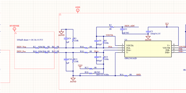
Test condition:
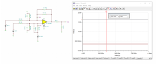
(1) Add voltage source to ISEN Neg=15V ISEN_Pos=15V ISEN_ADC(Vout) = 1.621V (wrong case, the right result should be 1.65V)
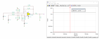
(2) Add voltage source to ISEN Neg=0V ISEN_Pos=0V ISEN_ADC(Vout) = 1.65V (right case)
(3) Add voltage source to ISEN Neg=0V ISEN_Pos=0.8V ISEN_ADC(Vout) = 1.65V+0.8V (right case)
Could you kindly provide you solution for high CM applicaition?