This thread has been locked.

If you have a related question, please click the "Ask a related question" button in the top right corner. The newly created question will be automatically linked to this question.

LMP7721: Current sensing using

Part Number: LMP7721
Other Parts Discussed in Thread: INA128, INA226, TINA-TI

Hello everyone! I have a big problem regarding my schematics...

To begin, I am trying to create a circuit that helps me measure the current on a Schottky diode that is polarized from 0.2 to 2.5V in 0.05V steps. The range of the current values is aprox. 1nA to 100mA. I've divided this range in 3 smaller ones, and tried to find a circuit to use for each one:

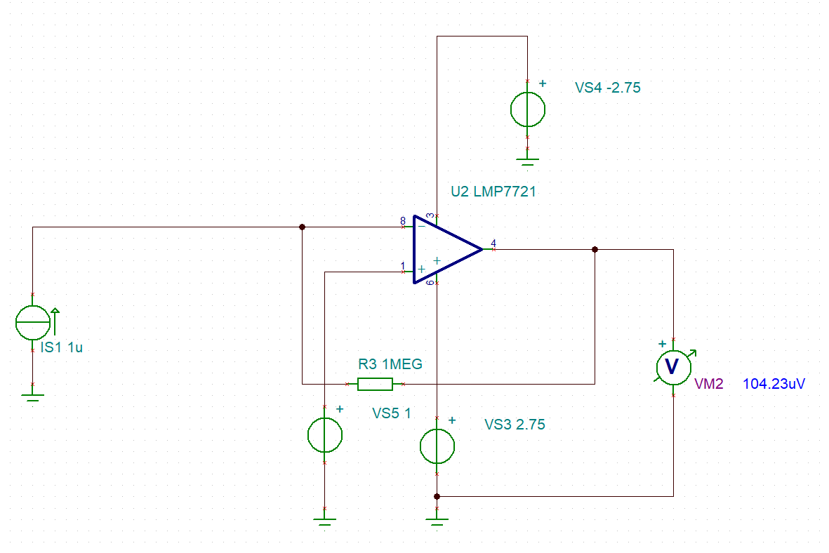
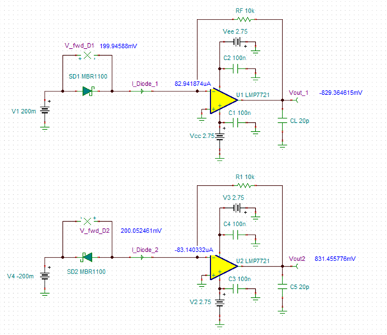
1. 1nA to 1uA - I chose the LMP7721, and I tried to configure it in TIA mode so that I can connect its output to an ADC and then to a MCU, but the problem seems to be that for my values, it returns negative voltages - I am not really sure how to work around this.

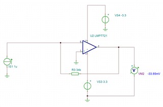
Something like that, after some corrections that I've got from another forum since I initially connected V- to GND......

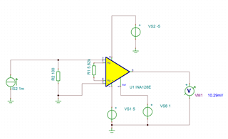
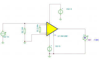
2. 1uA to 1mA using INA128 - here I chose a Rg for a gain of 20, but then again, after the corrections regarding V- connection I realised that the values are also negative.

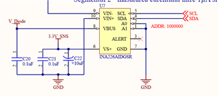
3. 1mA to 100mA - Using INA226 - didnt get to test this one, I've added a 0.75Ohm sense resistor for it, and it looks like this:

The first range using LMP7721 is the most important to the circuit.. can you help me find a solution regarding the configuration of this TIA in order to get some good values on the output?

PS: I know I am not good at designing circuits and those may have some mistakes, but I just need help here, because I don't know what to do about it.

  • Hi Alex,

    The first thing I notice about your LMP7721 circuit is that you are violating the maximum power supply voltage. See in the datasheet the absolute maximum rating is 6V and the maximum recommended supply voltage is 5.5V. You are attempting to apply (+3.3 – -3.3V) = 6.6V which will destroy the device in a real circuit. I recommend using +/- 2.75V supplies.


    Second, the transfer function for a TIA is –(I*RF). This can be determined intuitively and by ohms law. The two amplifier inputs must remain a "virtual short" therefore when current is forced across the feedback resistor (RF), only the voltage at the output can move. Try reversing the polarity of your current source.

    For the INA128, the transfer function function is (V+ – V-) * G = (0 – 0.1) * 20 = -2V. Try reversing your input pin connections.

    Regards and good luck with your design,

    Zach

  • Thank you for your reply!! Seems like I didn't pay enough attention to LMP7721 max voltage, I am sorry for that. I don't know what to say about reversing the current source, this circuit will measure the current on a schottky diode when forward biased - and I am a little confused by that and why its negative when I try to mimic it. When I've put the schottky diode that is standard in TINA-TI, and polarized it with a voltage source, the output voltage was also negative (bigger in value of course), so I think that my current source mimics that behavior.

    One solution that I found is adding a different voltage as a Reference instead of GND: 1V source for example and this gives me positive values.

    I've played a bit with the resistors values and got to the output modifying with 1mV per 1nA for LMP7721 and 1mV per 1uA for INA128.

    I am not sure if this is a good approach, but it seems like it's working. If you could give me your thought on this, it would be great

    Thanks again,

    Alex

  • Hi Alex,

    See the schematic below. We see two configurations, both measuring the current of a forward biased Schottky diode. One is configured to measure the current with a positive polarity, the other is configured to measure the current with a negative polarity.

    The forward bias voltage (~200mV) and forward current (~83μA) are essentially equal between the two, the only difference is due to the polarity of the op amp model's ~54μV of offset voltage.

    LMP7721_Diode_Polarity.TSC

    To reverse the polarity of your INA, you simple need to reverse the connection of your input pins. That is, swap the positions of Vin+ and Vin- across the 100Ω resistor.

    I hope this helps.

    Regards,

    Zach

  • Thank you, Zach! I will adapt my system accordingly!

  • Hi Alex,

    No problem, I am happy to help. I will go ahead and close this thread for now, good luck with your design.

    Regards,

    Zach