This thread has been locked.

If you have a related question, please click the "Ask a related question" button in the top right corner. The newly created question will be automatically linked to this question.

TIDA-010232: RisoN/P Calculation when only 1 "r" is present

Part Number: TIDA-010232
Other Parts Discussed in Thread: AMC3330

For the TIDA-010232 what is the order of operation in terms of closing and opening the switch.
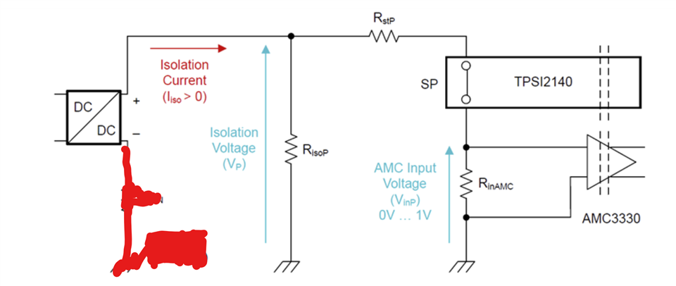
Based on the sample code and diagram below it seems like if you want V+ reading you close contactors for + and open - and vice versa.

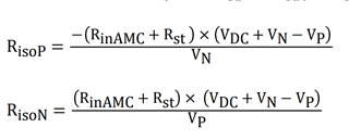
This only works under the assumption that there is a valid R for isoN and isoP. 

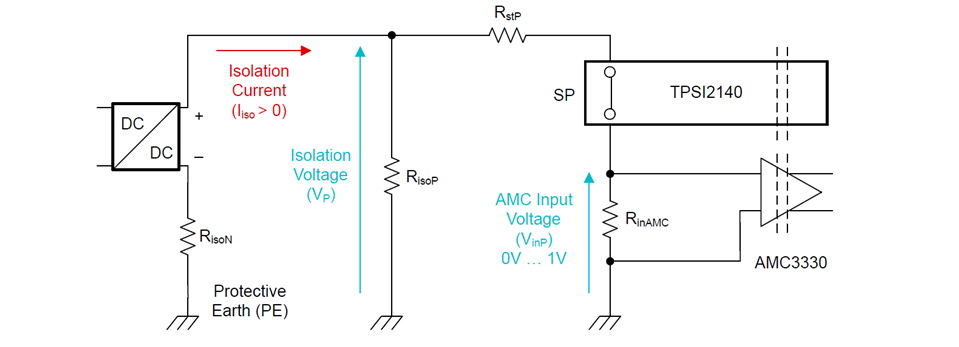
If the resistance is zero ie. only the positive end has a valid resistance, theoretically, you cannot have a valid reading since there is no voltage potential across RinAMC, since RisoN is zero the loop cannot be connected since there is not path to PE. 

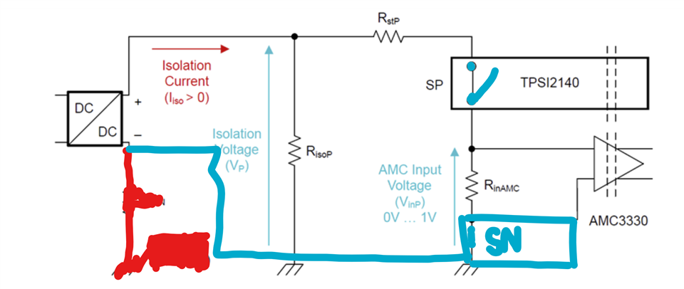
The only way would be to close SN and open SP as that way there is a path from PE.

I was wondering if there was any clarification regarding those situations where only 1 pole of the DC/DC is being faulted   

  • Hi,

    Thanks for reaching out.
    Lets suppose RisoP is 0 Ohm and RisoN is 1MegOhm, VDC = 400 V, RstP = RstN = 68 kOhm and RinAMC = 120 Ohms.

    Looking at Figure 1-5 (SP closed) ,this will lead to VP being 0 V. 
    Looking at Figure 1-6(SN closed), this will lead to VN = - 800 V.

    Plugging this into equations (13) and (14), we can see that RisoN will go to infinite, but RisoP will be calulated to 0 Ohms and we can detect the fault.

    RisoP = -((RinAMC +Rst) * (VDC+VN-VP))/VN = -((120+68k)*(800+(-800)-0))/800  = 0

    Hope this helps.

    Best regards,
    Andreas

  • Hi, Andreas,

    I think specifically the area I am a little unclear is how RisoN acts when SP is closed and how RisoP acts when SN is closed.

    Even in the solution above you are still assuming the negative end of the DC/DC is connected to PE?

    I guess this was the scenario I was wondering, where there is leakage current in only Risop and because there's no short on the - Line, the negative does not connect with PE. In this scenario, there is no voltage drop since the circuit is open and you won't be able to read the voltage drop from RisoP.

    The work around would be opening SP and closing SN to then

    So then to pickup the error on RisoP you would need to close SN instead of SP?

  • Hi Kevin,

    I think there is a general misunderstanding.

    We do not measure RisoP in figure 1-5 and RisoN in Figure 1-6.
    We measure VP when SP is closed (Figure1-5) and we measure VN when SN is closed (Figure 1-6).
    We always do both of these measurements.

    Then we use VN and VP to calculated RisoN and RisoP.

    We need both VN and VP to calculate RisoP or RisoN.


    So the flow is.
    Close SP -> Measure VP  -> open SP -> close SN -> Measure VN  -> use VP and VN with equations (13) and (14) to calculate both RisoN and RisoP

    We always do this complete flow.

    Hope this helps.

    Best regards,
    Andreas

  • Hello Andreas,

    Thank you for the clarification, I will look more into it.

    A follow up would be the equation used to calculate the Riso values are slightly different in the sample code,

     r_iso_n =  ((r_s + r_ns)*(r_s + r_ps)*(v_DC_N*v_DC_P + v_DC_P * v_iso_N    - v_DC_N * v_iso_P))   /(v_iso_P   *(r_ns * v_iso_N    - r_ps * v_iso_N    + v_DC_N*r_s + v_DC_N*r_ns));

        r_iso_p = -((r_s + r_ns)*(r_s + r_ps)*(v_DC_N*v_DC_P + v_DC_P*v_iso_N - v_DC_N*v_iso_P))/(v_iso_N*(r_ns*v_iso_P - r_ps*v_iso_P + v_DC_P*r_s + v_DC_P*r_ps));
    }
    Even if you sub Vn and Vp with the voltage divider Vin equation. I was wondering if there was any documentation on this
  • Hello Kevin,

    These equations in the design guide assume that the DC bus voltage is constant. Since we do a sequential measurement of VN and VP DC voltage can vary between these measurements.
    That's why we do a DC bus voltage measurement simultaneously with the measurement of VN and store the value in v_DC_N and another DC Bus voltage measurement simultaneously to the measurement of VP and we store it in v_DC_P.  

    The equations used in the code take this change in DC Bus voltage between measurements into account.

    Best regards,

    Andreas

  • Hello Andreas,

    Right now I am trying to simulate a fault I have a 100k resistor that is connect from the - end of the DC/DC to PE. with a RstP = RstN = 68 kOhm and RinAMC = 120 Ohms. I have a Vp of 95.8V Vn of 0 and the final RisoN is 13544 ohms, which is quick off. I am also testing this on a VDC of 100V instead of 400V is that causing the error?

  • Hi Kevin,

    Yes, testing at lower voltages will increase the error, since all measured voltages are proportional to VDC, while some of the error sources, like offsets are not, but 13.5k instead of 100k is to far off. I am expecting an error of below 10% for this case.
    So, in your setup you simulate RisoN = 100k and RisoP is an open circuit, right?

    Can you verify the system is working if you connect 100k on both ends.(between DC+ and PE and DC- and PE).

    Best regards,

    Andreas.

  • If I connect a 100k on both the +/- I get a Vp of around 80V and Vn of -20V, The Vn seems off because if both Vp/n should be +-80V to get around 100k

  • Hi Kevin,

    Sorry, for the delayed feedback, i was out of office for a few days.
    Yes, if RisoP and RisoN are symmetrical, also the voltages VP and VN should be similar. 
    Please check that the schematic is identical to Figure 1-4.

    And that only one switch is closed at a time.
    For measurement of VP, SP closed and SN open.
    For measurement of VN, SN closed and SP open.

    Best regards,

    Andreas

  • Hi Andreas,

    Is there an available pspice simulation for this circuit?

  • Hi Kevin,

    There is no complete PSpice simulation available, but we have models for the AMC3330  available which can be used to build a simulation deck.
    TPSI2140 can modeled by a ideal switch and the its' on resitsance.

    Best regards,

    Andreas