This thread has been locked.

If you have a related question, please click the "Ask a related question" button in the top right corner. The newly created question will be automatically linked to this question.

LM324: Shifting a variable range of negative input voltage to a fixed output voltage

Part Number: LM324

Hello,

I have a negative range of input voltage and I want to shift that input voltage to feed an ADC pin of an ESP32 microcontroller.

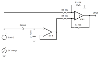
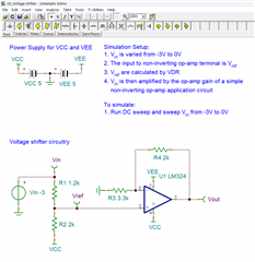
Initiallty, the input voltage range is -3V to 0V, so I tried using a simple voltage shifter that shifts the input voltage from -3V to 0V into 0V to 3V with the non-inverting op-amp configuration and it works.

However, later I found out that the input range may varies from time to time and is not fixed. Sometimes the input voltage is -5V to -2V, sometimes it is -2V to 0V. And since my input voltage does not have a fixed range, I need to change the resistor value multiple times. If I make my input voltage range bigger, than the output voltage would be smaller.

If possible I would want to shift the input voltage as it is for example:
-3V to 0V ---> 0V to 3V
-5V to -3V ---> 0V to 3V

Not:
-5V to 0V ---> 0V to 3V

Is there any IC or reference circuit to convert that input voltage to a fixed range positive voltage of 0-3V?

  • Hello Akmal,

    Try writing this voltage transfer function as a linear equation. At minimum, both ends of the input range must be known before the input is applied. In other words, in linear equation y=mx+b ; both m and b value changes due input change must be known before hand. Is the range of input available as two extra inputs?

    Give me an equation and I'll help you with a solution.

  • Hello Ron, my input comes from a sensor fabricated in the lab. I use one sensor at one time. But here's the thing: when it detects ions in the solution, it doesn't always give us a steady range of outputs typically in the negative range. That output is what I wanted to feed into my voltage shifter circuit to shift that voltage into positive range. The sensor does show results in a straight line, but only the voltage (x) changes, not the gradient (m). For the linear equation of y=mx+b, m is constant, x changes, and b changes with x.

    So, when the gradient stays the same, the range of values it shows is consistent. Let's say there's always a 3V difference from start to finish. When the sensor reading starts at -5V, it will end at -2V. If it starts to read at -4V, the voltage will end at -1V. No matter where it starts, it always ends up with that same 3V difference in voltage.

  • Akmal,

    If x = VIN, y = VOUT then linear equation is y = x - x(t0) ; clearly for time = zero ; y = 0 

    A transient simulation of this ideal circuit will output 0V to 3V as input increases by 3 over time for any value of "Start" voltage.

    How fast does your input change? You need to sample the initial voltage then open the switch for the rest of the input change time.

    The sim transient (Ctrl-Alt-t) works because the sample switch has a 1G off resistance so C1 voltage starts (and stays) at initial input voltage voltage.

    IOP1 should be a low input bias current op amp.  

    y eq x - x(t0).TSC