INA381-Q1: Oscillations on ALERT Signal

Part Number: INA381-Q1
Other Parts Discussed in Thread: UCC27424

Hello TI,

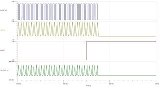
I am currently simulating the behaviour of INA381-Q1 during over current condition as shown in the below circuit. I have created an over current situation by placing a low resistance of 50 ohm across 28V which is connected to drain of the N-channel mosfet. Initially i have operated the device in 'transperant mode' by keeping the RESET pin low and observed expected behaviour from ALERT signal. Then during the over current condition, after 600us I made RESET high to keep the device in Latch mode. However, the ALERT signal didnt immediately go low instead It has oscillated for 25us before staying permanently low. Do you know why this 'oscillating' behavior occurs ? also I have disconnected ALERT signal from ENBA of mosfet driver(UCC27424) then the ALERT signal became low immediately without oscillations. Could you please look into this and advise the reason for this behavior ?

INA381A1Q1.TSC

Best Regards,

Manoj.

  • Hello Manoj,

    Please see this thread: https://e2e.ti.com/support/amplifiers-group/amplifiers/f/amplifiers-forum/1183274/ina381-ina381-alert-is-not-locked-for-the-first-time based on what I am seeing here I think that this looks more like a simulation artifact. The model contains a delay of 25µS that is probably not reflected on an actual device. I will need to look into how the actual device performs.

    Levi DeVries

  • Hello Levi,

    Thanks for the response. Please let me know once you hvae some update on the same.

    Best Regards,

    Manoj.

  • Hello Manoj,

    I performed a test on the actual device and found <1µS of delay from the time the reset pin is pulled high to the time the device starts to latch the output. I only tested 3 devices and this was the most delay I observed:

    The delay observed here is about 0.1µS, so I think it is sufficiently clear that the 25µS displayed by the simulation reflects a limitation of the model, not the actual device. The alert response is much better in reality.

    The only difference between the test I performed and the setup you showed me is that the input frequency I am using is only 20kHz.

    Let me know if you have any further questions,

    Levi DeVries

  • Hello Levi,

    Thanks for performing quick test on the actual device. However, I have couple of questions, firstly what is this input frequency of 20KHz that you are talking about ? Also, as I mentioned previously when i disconnect the ALERT signal from the Mosfet driver IC, I am not seeing this kind of behavior. Do you know the reason why this is happening only when I can connect the ALERT signal to Mosfet driver enable signal ?

    Best Regards,

    Manoj.

  • Manoj,

    Do you know the reason why this is happening only when I can connect the ALERT signal to Mosfet driver enable signal

    If you look at your circuit you will notice that the alert pin is tied to your gate driver IC's enable pin. When the alert of the current sensor triggers the gate driver will be disabled, cutting off the current to the MOSFET. In the transparent alert mode this will cause the alert to go high again, causing the MOSFET to become active. In this way you have a feedback loop that will constantly oscillate as long as the alert is operating in transparent mode. The frequency of this oscillation is dependent on the total delay of the signals propagating throughout the system, in your case it will be around 182kHz.

    what is this input frequency of 20KHz that you are talking about ?

    I don't have the MOSFET and gate driver you are using on hand so I simply used a test signal into the comparator input to test the transition time going from the transparent to the latched state. The signal I used was only 20kHz, but I think the results will be similar for your system as this is more of a time-domain effect than a frequency effect.

    Let me know if you have any more questions about this,

    Levi DeVries

  • Hello Levi,

    Regarding the ALERT signal you are right about transparent mode, but here i am operating it in Latch mode, in this case it shouldnt oscillate. Also, I would like to operate this in Latch mode in my application. Is it ok if i connect the Reset pin directly to 3.3V with a pull up to make it permanantly high to keep it in latch mode ?

    Best Regards,

    Manoj.

  • Hello,

    Is it ok if i connect the Reset pin directly to 3.3V with a pull up to make it permanantly high to keep it in latch mode ?

    Yes this will work fine, however if you cannot change the 3.3V you will have no way to turn off the alert pin without turning the device off completely.

    Regarding the ALERT signal you are right about transparent mode, but here i am operating it in Latch mode, in this case it shouldnt oscillate

    If you review my comments above, the latched mode is operating as expected, what you are experiencing is a delay that is present in the model when operating in a transient mode. Because of the delay latched mode does not activate immediately. I have tested the actual chip and this delay is not experienced in the actual device.

    Let me know if you have any more questions,

    Levi DeVries