This thread has been locked.

If you have a related question, please click the "Ask a related question" button in the top right corner. The newly created question will be automatically linked to this question.

CIRCUIT060002: Temperature sensing with NTC thermistor circuit

Part Number: CIRCUIT060002
Other Parts Discussed in Thread: TLV9002, , LM134, OPA2187, OPA4187, OPA187

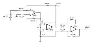
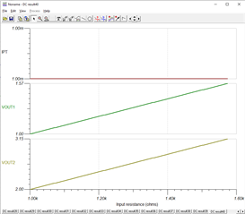
I was looking at this circuit CIRCUIT060002 in which temperature measurement is done using a NTC thermistor. The change in temperature will change in resistance but in voltage divider circuit, this will also change the current, right ? then the resistance change will not exactly equal to the voltage read by the opamp TLV9002. What is the accuracy of the measurement ? 

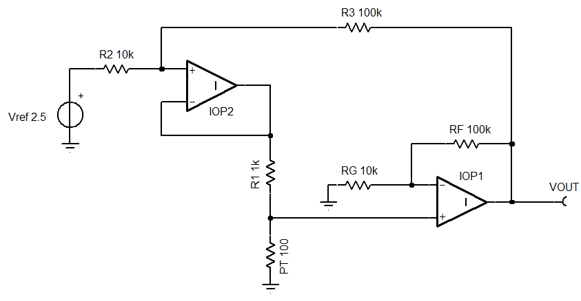
In my application I am looking for a circuit to measure the temperature between 0 to 150 degC. The measurement error or precision could be within +/- 1 degC which is fine. Considering CIRCUIT060002, what values should I use for R1, R2 and R3 ? and also Vref.  

  • Hello John,

    The circuit is not a linear conversion from NTC resistance to voltage. Over a large temperature range, this will become more non linear. If your application can correct for the non linearity, then this circuit topology can be used. 

    I suggested circuits for a linear R to V conversions in this thread; https://e2e.ti.com/support/amplifiers-group/amplifiers/f/amplifiers-forum/1311187/lmv612-lmv612/5022774#5022774

    Below is a simple linear conversion example.  The fixed current is Vref*(G-1)/(G*R1) ; where G =11 (IOP1) gain)

    So [-40C to 200C] (on PT100) becomes [0.641V to 1.34V]

    The gain is set by both R1 that sets the current and RF/RG+1 which amplifies the PT100 voltage.

    Is your NTC physically close to the NTC amplifier? (kelvin connection not needed)

    Can your application turn resistance into temperature for the selected NTC? (non linearity of NTC [T to R] is not corrected by amplifier)

  • Thanks for your reply. This look like a solution to me. I see that PT100 is used in the circuit you attached. We can also use PT100. with the two operational amplifier as your circuit diagram. We do not need very accurate measurement. 

    Can you please say something about measurement accuracy/error with the proposed solution you mentioned. Is that within +/- 5 degC or within +/- 2 degC or or within +/- 1 degC ? 

  • John,

    With everything else being perfect. This non-linearity error (for a PT100 table I found) will remain.

    The PT100 base resistance will be another source of error. Most options are 0.25% resistance or 0.6C or better.

    The circuit's resistance tolerances, op amp offset voltages, and Vref tolerance will add their errors. I expect 2C could be done without calibrations.  

    What is your most accurate refence voltage? (use ADC Vref to cancel out some Vref error)

    What is the desired output range? (should be a little less than your full scale read to allow for tolerances and allow little over range)

    Lastly what are your power supplies voltages?

  • Hello Ron Michallick,

    I am not sure which solution is better among the following three options. 

    1- The circuit diagram as mentioned in CIRCUIT060002. They use NTC. Can we use PT1000 instead ?  

    2- The solution you presented in the post you mentioned. 

    3- A constant current source 1mA using LM134 through PT1000. 

    The temperature range and the accuracy is mentioned already in the first post in this thread. We can even accept the accuracy/offset/error of +/- 1 degC.  

  • John,

    I need the answer for this question to know what path to take "Is your temperature sensor inside your application, very close to amplifier?

    If no, then a kelvin measurement of the sensor should be implemented.

    For +/-1C max error, I suggest an internal calibration of the R to V convertor. Otherwise all components must be very tight tolerances. 

    On left, current source as a Howland type. Alternative LM134 is 3% accuracy, but contains its own reference.

    In middle is selector for remote PT1000 or one of two cal reference resistors (only 1 cal R shown) (so convertor can provide calibration VOUTs)

    Two point calibration can remove linear errors in convertor only, any PT1000 error will remain.  

    Right section is an instrumentation amplifier (IA) which can be made from op amps and resistors or a chip IA


  • Yes, the temperature sensor PT1000 and the amplifier are located on the same PCB. I can use four four wire trace routing in the PCB design. They will be as close as possible on the PCB. Regarding the temperature measurement accuracy I can say that we are also find even with 2 degC off. This means we do not need very precise and accurate measurement. 

  • John,

    For that case, I'll suggest this version with two or three op amps OPA2187 or OPA4187 for low offset and low thermal drift. For on board usage, all the components will live in that 0C to 150C range. The fixed current is 1mA. There are two outputs VOUT1 uses less ADC range and output two uses more ADC range at added complexity. Vref should be same as ADC Vref so Vref error will cancel out.

    All resistors should be 0.1% or better and matching temperature coefficients. R1 should ideally have zero temperature coefficient because that scales the fixed V to I conversion. I can't say how accurate this will be because R1 will keylike be the key error.

    I'm also transferring post to precision op amps (for OPA187). They have more experience with precision calculations.    

    0C to 150C transfer function (1000.1 ohms to 1574.4 ohms) [values minimizes error based on 0V, 75C and 150C points]

    Additional circuity can allow getting full range of ADC range 0V to 3.3V, but that may introduce more error than it removes. 

    Rev2.TSC