This thread has been locked.

If you have a related question, please click the "Ask a related question" button in the top right corner. The newly created question will be automatically linked to this question.

AMC3301EVM: Was there a reason you went from 2 pins to 3 pins?

Part Number: AMC3301EVM

We are still learning what the problems are.

Firstly, we were getting spurious noise on our AC shunt measurements on some of the boards. After investigating more, we think this is occurring on the 2 pin boards, but we are not entirely convinced.

We ended up just switching boards until all signals were smooth.

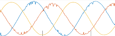
You can see here that one of them was fine and the other two have this noise on them. This is passed through an ADC so this representation is a reflection of the sampling frequency and its ability to process what seems to be higher frequency noise.

Secondly, we were playing around in the lab and noticed that the 3330 board just cannot function properly when HGND and INN are connected because the waveform becomes severely distorted by what looks like 50Hz ground noise. Now, obviously you say that they should be connected; so, this makes sense.

But, for the 3301 (or 3302), when we connect HGND and INN, it pulls OUTN and OUTP apart, which seemingly adds a DC bias to the measurement, sometimes to the extreme; this means we get premature clipping.

  • Hi Greg,

    Can you tell me a little about your application?  Also, I have a few more questions for you.

    Firstly, we were getting spurious noise on our AC shunt measurements on some of the boards. After investigating more, we think this is occurring on the 2 pin boards, but we are not entirely convinced.

    We ended up just switching boards until all signals were smooth.

    What boards are you talking about?  The AMC3301EVM?  What do you mean by 2 pin boards?

    Secondly, we were playing around in the lab and noticed that the 3330 board just cannot function properly when HGND and INN are connected because the waveform becomes severely distorted by what looks like 50Hz ground noise. Now, obviously you say that they should be connected; so, this makes sense.

    But, for the 3301 (or 3302), when we connect HGND and INN, it pulls OUTN and OUTP apart, which seemingly adds a DC bias to the measurement, sometimes to the extreme; this means we get premature clipping.

    The HGND needs to be connected to the INN pin.  Where do you connect them?  Can you send me a schematic or block diagram of your system?

    Thanks.