A related question is a question created from another question. When the related question is created, it will be automatically linked to the original question.
If you have a related question, please click the "Ask a related question" button in the top right corner. The newly created question will be automatically linked to this question.
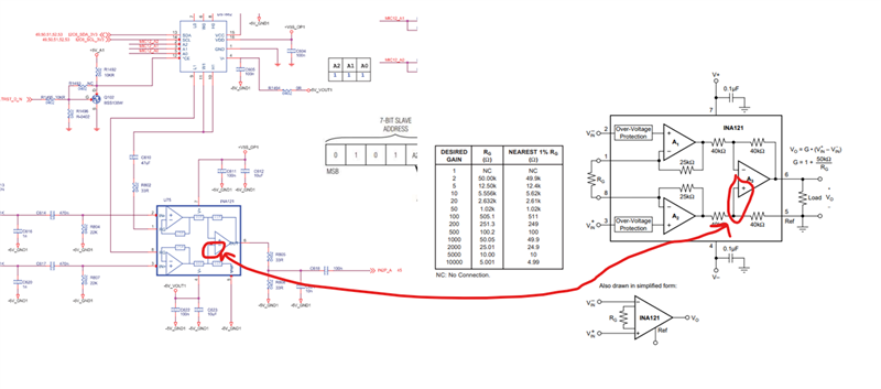
Is the goal to design a programmable gain using the DS1882? My concern is that there is potential for stability issues. I attempted to simulate this but do not see any ringing on the output. Typically we recommend the gain set resistor to be as close to the RG pins as possible to minimize any capacitance hanging off of the RG pins. The Rg pins are very sensitive and special care is needed in layout to get the gain resistor as close to the pins as possible.
I would recommend using a device that is designed specifically for programmable gains such as the PGA2500 or PGA2505.