This thread has been locked.

If you have a related question, please click the "Ask a related question" button in the top right corner. The newly created question will be automatically linked to this question.

INA226: Measuring flow sensor output from 4-20mA with INA226 breakout board and Raspberry Pi 4B+

Part Number: INA226

Hello everyone,
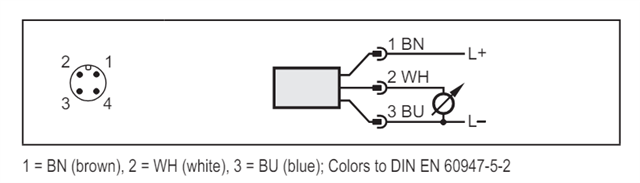
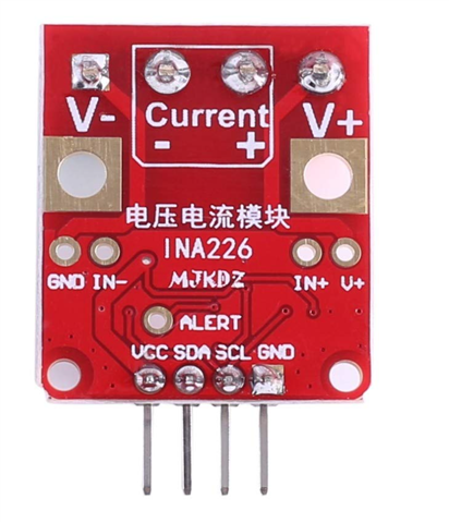
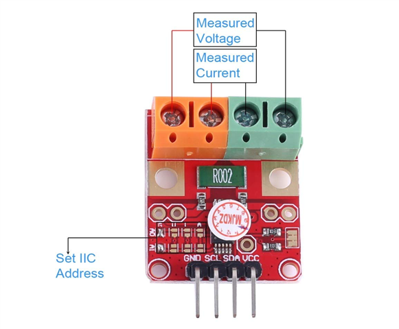
I have a small project to measure the flow output of a flow sensor (wiring diagram below) to the INA226 breakout board (wiring diagram below) and to a Raspberry Pi 4B+. Since I am not familiar with electrical work, I wanted to get some opinions on my approach to the problem.

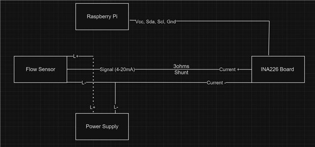
I am imagining the wiring diagram would look like this:

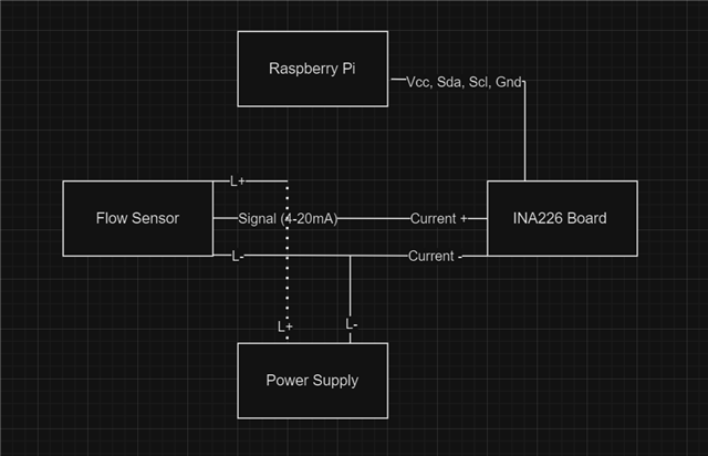
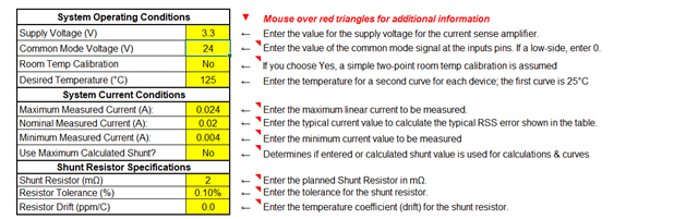
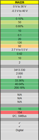
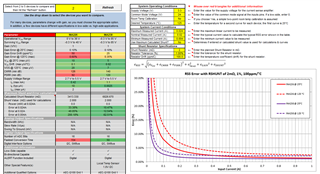
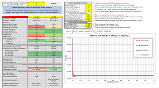
Afterward, I would use a Python library like this: https://github.com/e71828/pi_ina226/tree/main to query the current value from the INA226 board. Is this a good plan to tackle the problem? Additionally, since I need to measure between 4-20mA, what would be my rough measurement error with an INA226 and the R002 resistor on the board for this problem? 

  • Hi Peter, 

    The approach looks fine to me. I would reccommend using this TIPL to choose a shunt resistor as it depends on multiple factors based on system design: https://www.ti.com/video/6076324596001. We also have a digital power monitor tool which can help choose a shunt: https://www.ti.com/tool/download/SBOR021, https://www.ti.com/lit/an/sboa511a/sboa511a.pdf. Lastly, we have a error calculation tool that may help: https://www.ti.com/tool/CS-AMPLIFIER-ERROR-TOOL. Please let me know if you have any questions!

    Best,

    Mohamed 

  • Hey Mohamed,

    Not sure if I understand the error calculation tool correctly but I have the Pi powering the INA226 so the supply voltage will be 3.3V, the Common Mode Voltage is probably coming from the power supply to the flow sensor, and the Current + on the board so that will be 24V. I want to measure between 4-20mA so the range in Amp is 0.004 to 0.024A. The resistor on the given board is R002 so 2mOhms. After putting in my values, the error rate seems to be quite high. 

  • Hi Peter, 

    The biggest contribution to your error calculation could be coming from your shunt resistor. Because your shunt resistor is so small, it means the voltage drop across it is also small. The error at this point is mostly dictated by offset, and could be calibrated out. Alternatively, you could use a larger shunt resistor. 

    Using a 2mΩ shunt resistor: 

    Using a 100mΩ shunt resistor: 

    Best,

    Mohamed 

  • Can I add another 3-ohms resistor in series with the R002 resistor on the board to increase the overall resistance? The new diagram would look like this:

    Does it matter whether the new resistor would be on the high side or low side?

  • Hi Peter,

    You could add a series resistor as a shunt, however it would add some error because of the resistor tolerance. Theoretically that approach should work fine, however I'm not very familiar with the Adafruit INA226 board. Please let me know if you have any further questions! 

    Best,

    Mohamed