TLV7031: 150V Transient Durable Digital Input

Part Number: TLV7031
Other Parts Discussed in Thread: TLV7032, TINA-TI

Tool/software:

Hello,

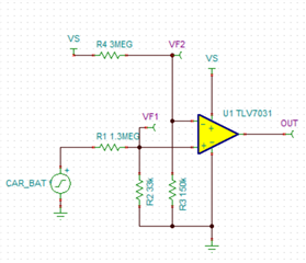
I am designing a digital input circuit that must withstand 150V transients. The operating temperature range is -40 to +85 degrees Celsius, and it needs to have low power consumption (less than 10 µA).

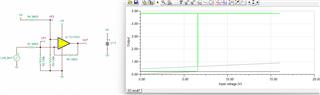
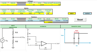
The schematic and simulation are attached.

comp_input.TSC

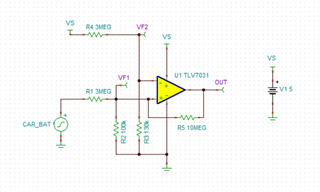
Could you please verify if the resistor values are suitable for the desired application, or if they are too large?

Best regards.

  • Hi Egemen,

    The resistor values are suitable per your power requirements.

    Generally, we try to keep the feedback resistor (R5 on your schematic) value low (1MEG to 2MEG maximum). This is because hysteresis depends on the output of the comparator charging or discharging any parasitic capacitances on the non-inverting node of the comparator. The timing for the non-inverting input to reach your calculated voltages for hysteresis is related to the size of R5, because R5 limits the current from the output to the non-inverting node. Too large of a feedback resistor would "slow down" hysteresis and the behavior may deviate from what you want in a physical circuit.

  • Hello,

    When the feedback resistor (R5) changed to the 1MEG the simulation result got weird. The simulation result is attached.

    What is causing this problem?

    Best Regards.

  • Hi Egemen,

    You'll have to adjust the other resistors as well per your VL and VH requirements if you adjust the feedback resistor. We have a cookbook that goes over how to choose external resistor values for a non-inverting comparator with hysteresis: Non-inverting comparator with hysteresis circuit (Rev. A).

    Regards,

    Ho

  • Hello Ho,

    Since there is no voltage divider at the input side, the application note you sent may not apply to our situation. Is there any other application note for choosing external resistor values?

    Best Regards.

  • Hi Egemen,

    We have an excel tool that helps with adjusting hysteresis values with a voltage divider on the input voltage. On the "Input Voltge" cell, select "HIGH" and it will place a voltage divider at the input. The rest of the parameters can be adjusted per your requirements.

    I'll attach the excel tool here:

    Hyst Tool.xlsm

    Hope that helps,

    Ho

  • Hello Ho,

    The Excel tool result is attached,

    I have several questions about the design.

    1-There is no R1 resistor in our design so can we neglect it?

    2-RA and RB calculated for 130V input but can the IC be durable for ISO7637-2 pulse 3b transient?

    3-Since there is a 7mV internal hysteresis can we operate the circuit without 1Meg positive feedback resistor?

    Best regards.

  • Hi Egemen,

    1. The excel tool calculations are made with R1 in mind. Neglecting it may cause your hysteresis values to deviate from what you've entered. You'll have to do the calculations with R1 = 0 to verify if neglecting it is acceptable.

    2. To avoid damage to the TLV7031, you will need to make sure that the voltages, currents, and temperatures that the device is exposed to is within the values of the absolute maximum table:

    3. This depends on the system requirements. If a typical value of 7mV internal hysteresis is sufficient, then you won't need to implement external hysteresis using discrete resistors.

  • Hello Ho,

    At the input side our voltage divider resistors 1.3Meg and 33k so the hysteresis shall be (R1/R2 * int hysteresis) which is around (39.3 * 7mV = 275.75mV) in our case, is that correct? 

    If it is correct 275mV hysteresis is enough for the design.

    Best regards.

  • Hi Egemen,

    Internal hysteresis does not get multiplied by the resistor divider at the input.

    Total Hysteresis = Internal Hysteresis + External Hysteresis

    275.75mV = 7mV + External Hysteresis

    This means that you will need a resistive network (including a feedback resistor) that provides 268.75mV of external hysteresis. You can do this per your own calculations or adapting your system to the tool that was posted. You can enter 7mV into the cell "hyst_int (mV)" which would take into account a non-zero value for the comparator's internal hysteresis.

  • Hello Ho,

    There is a paragraph about hysteresis in the datasheet on page 27.

    "First, choose a target range of hysteresis to achieve. For this design example, 50mV of hysteresis will be the target. Since the TLV7032 already has 10mV (typ) of internal hysteresis, the voltage output from the TMR Rotation Sensor should be scaled down by a factor of 5. This way, the 10mV of internal hysteresis gets scaled up by a factor of 5, resulting in 50mV of hysteresis."

    About the previous question isn't it the case?

  • Hello, Our team is on holiday and will get back to you next week.

  • Hi Egemen,

    What I meant was that the internal hysteresis of the comparator remains 7mV. Looking at your TINA-TI simulation as an example, let's assume Vs = 5V, which means that the voltage at IN- would be 238.1mV. With 7mV centered around IN-, the trip points for the comparator would be VH = 241.6mV and VL = 234.6mV. The trip points for CAR_BAT would then be VH = 9.7592V and VL = 9.4764V. The difference between these two values is ~282mV. By voltage dividing the inputs, you change up the hysteresis trip points of the comparator such that you effectively "scale up" the hysteresis from the input's perspective, but the comparator still has 7mV of internal hysteresis.