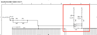
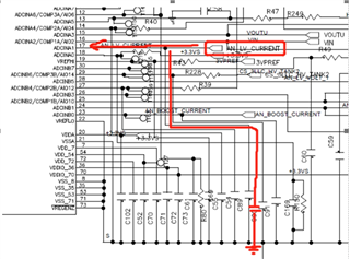
LMP8640: Abnormal output current value

Part Number: LMP8640

Tool/software:

Hi team,

LMP8640 is used on 6KW module inputs 600V and carries 20A, the current sampling is too small and the defective rate is 2/100. The root cause has not been found yet. Please assist in technical docking and arrange failure analysis of deviation materials to confirm the cause of the difference in op amps.  Customer has done ABA swap
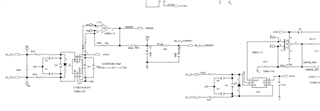
The verification information is as follows:
The input is DCDC 600V DC, the output voltage is 27.5V, the load is CC load, and the current error test requires 3%.At present, two units have a current sampling error of 12.9A when the input voltage is 600V and the load is 20A, which exceeds the test range of 13-28A. When the load is 30A, 50A, and 80A without calibration, the difference from the actual value is about 9A. After ABA verification, it is confirmed that it is related to the difference in current amplifiers.

600V with load 20A, output current display 12.9A.

600V with load 50A, output current display 39.7A

600V with load 80A, output current display 69.7A

Can you help review if this is application related or quality issue? Thanks!

  • Hello Zoe,

    Is this not above the VCM limit of the LMP8640? (LMP8640-HV 76V max)  I do not see a floating GND pin connection so I assume GND is the V- pin connected to GND.  If they are measuring low side I could not tell from the schematic.  I would like to know what is the VCM input of the device.

    Also what are the values of the input resistors.  The input bias current could be the issue.  If they measure before and after the resistor this could tell them if there is a problem at the input and if there is more input bias current than expected.

    Regards,

    Javier Contreras

  • Hi Javier:

    1. The output voltage of our module is 27.5V, which does not exceed the maximum voltage of 76V of the device;
    2. Resistors R191 and R192 (resistance value: 15W; 0.2mΩ; ±1%) are connected in parallel, and resistors R98 and R97 (resistance value: 1/10W; 0Ω; ±1%).

    Any further comments on this?

  • Hello Zoe,

    Normally I would account this to layout as parallel resistors can be an issue if the current is not split evenly as expected due to resistance from your layout.  Resistance and current density could not be distributed evenly as expected.  You could have more current on one resistor and measuring across the other.  Also besides layout you can also see issue with solder as solder can have a large resistance relative to your Rshunt values.  This could also lead to resistance and current mismatch on each leg of your parallel resistors.

    If you can measure the voltage across each resistor and the inputs of the LMP8640 this will confirm this theory.  

    Regards,

    Javier