Other Parts Discussed in Thread: TL431, TLV3201
Tool/software:
Hi Sirs,
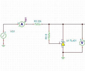
I am utilizing the LMH6642 as a comparator with single power rail 3.3V. The datasheet for the LMH6642 indicates that the maximum input voltage range is +/-2.5V. Does this imply that I can safely apply a common-mode input voltage ranging from +2.5V to -0.6V without any problems?
If this is not advisable, could you recommend a comparator that can handle an input voltage range from -0.6V to +2.5V with a single 3.3V power supply?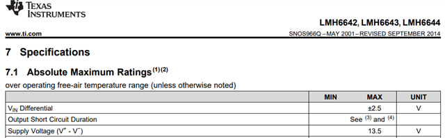
Thank you and Best regards,
Wayne Chen
07/10/2024