Other Parts Discussed in Thread: OPA615, OPA860, OPA1S2385
Tool/software:
Hi team,
The customers want to select an op-amp and the requirement is as below:
Differential signal to single-ended signal
3.3V supply,
input signal differential swing 550mV
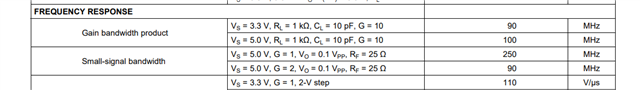
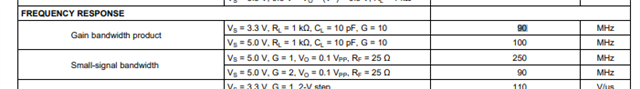
Bandwidth 80Mhz
Input signal impedance 100ohm
I think that OPA1S2384 is an option. And do you have better suggestion?