TL072: Abnormal voltage generated after voltage switching

Part Number: TL072

Tool/software:

Hello, our company purchased TL072CDR from TI Store. During the PCBA testing at the factory, we found that out of 100 PCBA units, 21 had the following voltage anomaly with the TL072:

The main issue occurs when switching from a negative voltage (-10V) to a positive voltage, resulting in an abnormal voltage. However, there are no problems when switching from negative to negative, positive to positive, or positive to negative voltage. The design and other electronic components have not been changed (in mass production for over 5 years). When the faulty TL072 is replaced on other PCBA units, the abnormal condition still follows the TL072.

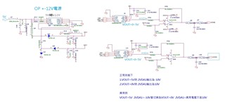
As shown in the attached circuit diagram, under normal conditions:

When VOUT=5V, 2VDA1 outputs -10V
When VOUT=0V, 2VDA1 outputs 10V
In abnormal conditions:
When VOUT=5V, 2VDA1 outputs -10V, but when switching to VOUT=0V, 2VDA1 shows an abnormal voltage instead of 10V.

  • What exactly do you mean with "abnormal"? Please show an oscilloscope trace with the input voltage, the voltage at pin 2/6, and the output voltage.

  • Something does not make sense tome. Looking at the schematic, 

    when VOUT = 5V , 2VDA1 should be 0V (not -10V as stated);

    when VOUT = 0V, TL072 would overscale, hit the 12V rail (but it is nor R2R op-amp), so 2VDA1 would be uncontrolled somewhere about 10...11V.

    It looks there is nothing abnormal, just the circuit is weird. Probably wrong design.

    To get the desired operation, you should:

    Change R766, R781 to 20K.

    Add 20K resistors in parallel to R767, R782.

    Then it will be working as required, but will be giving +/-10.05V, as the feedback resistors are not exactly 40K, but 40.2K.

  • Assuming that "E2.5V" is 2.5 V, the circuit is correct.

  • You are right, it looks like "E2.5V". I thought it was E2=5V (blurry on screen). Why use a separate REF/2 if he already has 5V reference for the DAC?

    There is another funny thing -- the filter 4.7uH and 22nF resonates at 500kHz (very-very roughly), which is close to the open loop GBW (assuming the op-amp has GBW=3MHz). So it might oscillate and give wrong DC output (capacitance at the inverting input adds to instability). Oscillation may be marginal -- whistles on some and quiet on others samples of the same op-amp.

  • Hi,

    the measurement records of TL072 are attached. Please help confirm the cause. Thank you.

    TL072 measurement record.pdf

  • Hi Dennis,

    As expected, there is oscillation preventing the op-amp settling at the correct voltage level. The oscillation is caused mostly by the LC filter at the output. (Purpose of this filter is obscure, but its series resonance is at about 500kHz.) To avoid oscillation, I would move the loop gain bandwidth either below of above this 500kHz. The easiest to try is to connect 47pF capacitors in parallel to R765 and R780. This would bring the loop GBW to 3MHz which is the natural GBW of the op-amp, and hopefully the oscillation will stop.

  • Dennis,

    Hello Dennis,

    My suggestion is to use a slower op amp that can't respond (not enough BW) to the output resonance.

    Alternative is to remove bandwidth from TL072C, see R6 and C2. 

  • Hi Alex, sorry for the late reply! Thank you for your suggestion. After paralleling the 47pF capacitor with R765 and R780, the resonance issue was resolved!

  • Hi Ron, sorry for the late reply! Thank you for your suggestion. Removing the bandwidth of TL072C also solved the resonance issue!