OPA2990: OPA2990

Part Number: OPA2990
Other Parts Discussed in Thread: THP210, TINA-TI, PGA855

Tool/software:

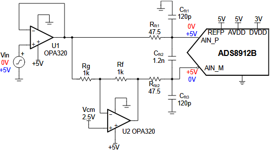
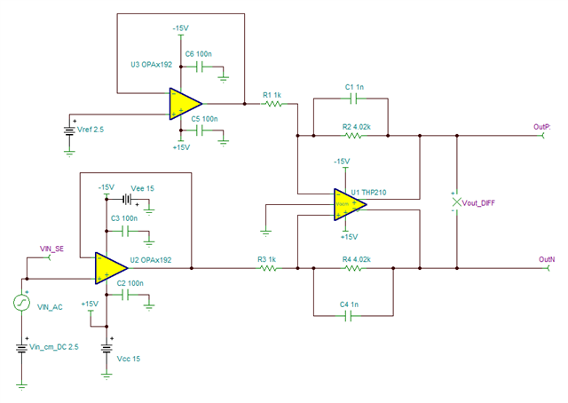
hi i need single ended to differential Converter circuit any ref design kindly suggest.

Requirement:

1.using op-amp or any other device.

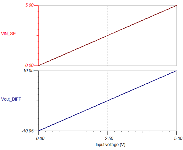
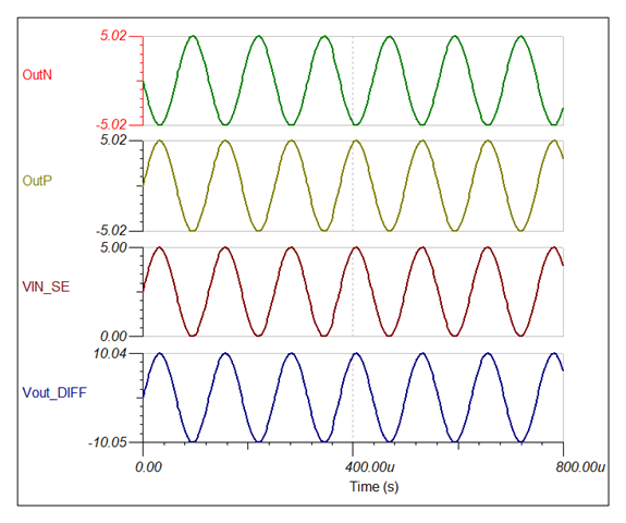
2.input (0-5V )  I NEED out put -10/+10 volts  differential.

3.it should work both AC & DC  (AC frequency 5hz to  8khz.

input driving from NI Card 10mA max .

Kindly suggest.

Regards,

shivaraj.r   

  • See the Single-ended to differential using a two op-amp circuit. For your ±10 V outputs, you need more amplification.

    You can use any opamp that has appropriate electrical characteristics. What supplies do you have available? Do you need a drive strength of more than a few mA? How much accuracy do you need?

  • thanks for suggestion,  i have +/- 15V  power supply for op amp and i have 5volts supply i can generate reference voltage and o/p drive current 10mA max we are using above also ok .

    i have tina software i will simulate and update.  

  • i tried  output not coming properly it should not cross +/-10v   and wave form not coming

    given input sign wave 3v 1khz

  • In the question, you wrote that the input voltage range is from 0 V to 5 V. But here, you're using from −3 V to 3 V. Please specify which one is correct.

    What is the absolute range of the output voltages? From 0 V to 10 V, or from −5 V to 5 V?

    This circuit does not have the ×2 amplification that you want.

    The opamp will not be able to handle voltages outside its own supplies. At least use ±15 V supplies.

  • hi input dc 0-5 volts 

    AC -5 to +5 v

    variable output +/- 10 volts   in-between.

  • When the outputs are between ±10 V, then the differential output voltage is ±20 V.

    Please specify the absolute and differential output voltage ranges that you actually want.

  • I have to convert single ended to differential output.

    Single ended voltage is 0 to 5 volt
    and i need differential output from +10 volt to -10 volt.

    Like,
    For 0 Volt : Requires -10 volt
    For 0.5 Volt : Requires -8 volt
    For 1 Volt : Requires -6 volt
    For 1.5 Volt : Requires -4 volt
    For 2 Volt : Requires -2 volt
    For 2.5 Volt : Requires 0 volt
    For 3 Volt : Requires +2 volt
    For 3.5 Volt : Requires +4 volt
    For 4 Volt : Requires +6 volt
    For 4.5 Volt : Requires +8 volt
    For 5 Volt : Requires +10 volt

  • And what about AC?

  • hi sorry for delay i am able to achieve dc gain, below circuit. also i need ac also 

    kindly suggest any circuit both ac and DC

  • Hi Shivaraj,

    There are different methods to perform single-ended to differential conversion.

    As shown on the posts above, one popular method uses two-op amps: the first op-amp stage is configured as a buffer amplifier, followed by second amplifier stage configured as an inverter. The application note that Clemens suggested, explains this circuit in detail - See the Single-ended to differential using a two op-amp circuit

    A second method is to use a Fully-Differential Amplifier (FDA) such as the THP210.  You can add buffers at the inputs of the FDA, if the sensor or circuit driving the FDA requires a high-input impedance.  One advantage of the FDA, is the differential output voltage common-mode is set with the FDA's VOCM pin. See the Single-ended-to-differential circuit using an op amp and FDA for bipolar signals, application note.

    For example, the circuit below with the THP210, converts a 0V to 5V input signal into -10V to +10V differential. 

    In the simulation below, the input single-ended input signal is centered at +2.5V DC input common mode, with a Vin = 2.5Vpeak and frequency of 8kHz. The THP210 converts the single-ended to fully-differential with Gain=4x. The VOCM pin is set to 0V (GND) and therefore, the output common-mode voltage is fixed at 0V. The device produces a ±10V fully-differential signal centered at 0V.  See below:

    OPA192-THP210 TINA-TI simulation:

    OPA192_THP210_7-19-24.TSC

    If you have further questions, clearly define the following:

    1) Single ended input signal

    Input voltage DC common-mode voltage

    - AC input signal amplitude

    1) Fully-differential output signal:

    - Output common voltage

    - Output voltage range and/or gain of circuit.

    Thank you and Regards,

    Luis  

  • hi thanks  but i need  AC and DC  both should work same circuit.

    some test case i am driving input from PXI AO Card DC gain test.

    ...

    in dc gain test differential Output +5v, 3.7v, 1.85  and  -5v, -3.7v, -1.85 some test case + volts required and some test case -v required

    some test case i am driving input from PXI AO Card AC Frequency response test.

    above circuit i simulated working fine my requirement but i need dc gain test also  

    it is possible same circuit both AC & DC test 

    input signal 0 to 5 for dc 

    input signal 0 to 5 Peak   or  we have input ac peak to peak any voltage i need +/- 10v   

    current max 10mA 

    Regards,

    shivaraj.r

  • for Frequency response test

    above test case 3.7V Peak is the required output form our circuit different frequency above shown are 17 hz to 2.6khz max

  • Hi Shivaraj,

    Sorry, I don't follow the explanation about the DC voltage and AC range input and output requirements.

    What gain (or gains) do you need to support for the DC and AC signals? Do you require different gains for different input signal conditions?  Is the DC and AC signals provided through separate inputs? OR is the DC and AC signal on the same circuit input? Please define the gain of the circuit.

    For example, on your last post, the THP210 gain can be configured for a gain of 1V/V by selecting the input and feedback resistor components. If you circuit requires to support an AC input signal of 3.7Vp and provide a 3.7Vp output, the THP210 can be set on G=+1 by changing your feedback resistors to 1kΩ. This circuit will also gain the DC signals at the inputs by the same gain of 1V/V.  If you don't want to amplify the DC component of the signal, you could AC couple the input using a capacitor and set the circuit on a filter configuration with a response of 17Hz to 2.6kHz.  

    If you require a device with programmable/selectable gain, the PGA855 can work, providing single-ended to differential conversion, offering binary programmable gains of 0.125, 0.25, 0.5, 1, 2, 4, 8, 16V/V.  The device will offer the same gain for the DC and AC signals, but you can re-configure the gains in the range of 0.25V/V to 16V/V  for the different cases. 

    Thank you and Regards,

    Luis