This thread has been locked.

If you have a related question, please click the "Ask a related question" button in the top right corner. The newly created question will be automatically linked to this question.

OPA310: High Current Op Amp Driver for Audio Over Light Project

Part Number: OPA310

Tool/software:

Hello E2E Experts,

Good day.

I am working on a project to modulate an LED with audio from our Laptop computer.

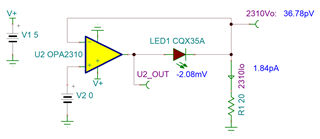
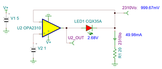
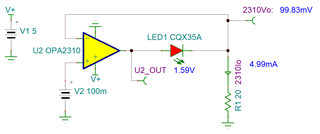
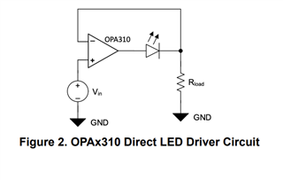
For this project, I am utilizing the OPA310  high-current Op Amp Driver, a crucial component as described in Figure 2 of our article 'Benefits of Op-Amps with High-Current Outputs.' The audio from the Laptop will be the Vin port in Figure 2, serving as the input for the LED modulation.

My understanding is that the audio should have a voltage level between 0 and 1 volt to do this. 

What do you think is the best way to accomplish this?

To explain further,

Looking at Figure 2, Vin is the modulating voltage for the LED and picking Rload for the LED current.
So, the voltage from the laptop's 3.5mm jack is AC since it drives headphones. 
If  I use the 3.5 mm jack as the Vin, only the positive voltage will be used since the OPA310 operates with a 5 Vdc supply.
That being the case, I must run the audio 3.5 mm jack voltage into another single rail noninverting op-amp that injects a bias of 2.5 the audio rides on.
Since this single rail noninverting op-amp does not need to supply the current to drive the LED, I could use a low-noise variety.
Is this the correct way of thinking?
Regards,
TI-CSC
  • Hi TI-CSC,

    I'm not entirely sure. It depends on what you are trying to accomplish. 

    So when we have a voltage of 0V on the input, then the op amp won't drive the diode since the negative input will also be 0V. 

    However at 1V, then the op amp is going to drive the output hard enough to overcome the diode drop and match the inputs as close as possible. In this example the output goes to 2.68V to get the inverting input to be about 1V.  

    You can also see this happen when applying 100mV on the input as well. The output adjusts to get the inverting input to match the non-inverting input. 

    The only time the diode will be turned off is when the input is at 0V. So with a DC bias, the LED will always be on, with varying brightness levels depending on how much current the op amp is driving. 

    If you only care about the amplitude of the signal, why not run it through a halfwave rectifier or full wave rectifier? 

    Best Regards,

    Robert Clifton