This thread has been locked.
If you have a related question, please click the "Ask a related question" button in the top right corner. The newly created question will be automatically linked to this question.
Tool/software:
Hi,
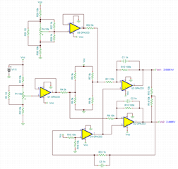
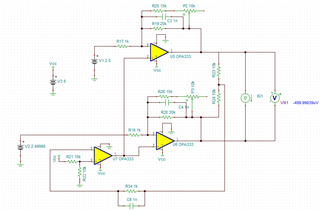
I tried a stability analysis of the adjustable fully differential amplifier design attached, but ended up with some unstable output. Can you please help to resolve the stability analysis of this design.
Best Regards,
Kavindu
Hi Kavindu,
The image below is all about biasing voltage and DC operation. I do not know what you are trying to do. There is no AC signal in the schematic.
I do not know why your gains are configured so high, but the circuit is operating in DC now. Please let me know if you need additional assistant.
Best,
Raymond
Hi Raymond,
Sorry if I have not supplied enough information. This circuit is intended to be used with a strain gage full bridge which is represented by R5,R6,R7,R8 in the design. In fact I'm concerned on the stability analysis of the circuit either in time domain or frequency domain. That is why I attached a current generator with step input. Can you propose any method if what I selected was not ok.
Best Regards,
Kavindu
Hi Kavindu,
his circuit is intended to be used with a strain gage full bridge
How about INA333 or similar low voltage instrumentation amplifier. The IA should be similar to OPA333 in Si design. Instrumentation amplifier is used as the standard strain gauge amplifier for the sensing application. The strain gauge may be used in mechanical systems to measure forces such as tension, compression, and torsion etc..
ht, tension, stress
We have many other low voltage instrumentation amplifiers to choose from, see the link below. Enclosed two application notes as well.
https://www.ti.com/amplifier-circuit/instrumentation/overview.html
https://www.ti.com/lit/an/sloa034/sloa034.pdf
If you tell me the highest voltage available in your PCB design and application type, I may be able to suggest something better or higher performance or other input and output design requirements.
Best,
Raymond
Hi Raymond,
Yes, agree with you. But I'm looking for a differential output design where the INA output is single-ended.
Best Regards,
Kavindu
Hi Kavindu,
Here are couple options for FDA output design. These are programmable gain IA.
https://www.ti.com/lit/ds/symlink/pga855.pdf
If you do not see what you like, we can convert the single ended output to differential output.
Best,
Raymond
Hi Raymond,
Thanks for suggestions. Please propose how we can convert a single-ended to differential ended. Because that 'd be a good lesson for me.
Best Regards,
Kavindu
Hi Kavindu,
Here is the application note.
https://www.ti.com/lit/ug/tidu038/tidu038.pdf?ts=1723654108539
I can help you to simulate something tomorrow, if you decided which IA will meet your design requirements. INA849 is the latest ultra low noise IA, but the minimum supply voltage needs to be 8V in single supply, +/-4V in dual supply. We have a wide range of pricing and performance IAs to choose from.
Best,
Raymond
Hi Kavindu,
Here is another simple way to convert single ended output to differential input, see the simulation.
THP210 SE to DF Output 08152024.TSC
If you have other questions, please let me know. If our support answered all your questions, please close this thread.
Best,
Raymond
Hi Kavindu,
I am going to close this query.
If you have other questions, please let me know.
Best,
Raymond