TLV9001: How to design breathing LED function by current sink circuits?

Part Number: TLV9001
Other Parts Discussed in Thread: SN74LVC1G07

Tool/software:

Hello,

We would like to design a breathing LED function. Can we implement breathing function by TLV9001 current sink circuit as below circuits? Is this correct?
Could breathing PWM be controlled by Vx or by 3.3V power source?

Or....Could breathing PWM be controlled by 3.3V power source to circuit?
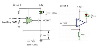
Thanks,
Hugo

  • Hello Hugo,

    The left circuit is good for DC current control, the right side is fine in theory but could be problematic in practice.

    For PWM input, make sure loop is fast enough for acceptable performance on left side. Almost certain problems on right side.

    Current control is best way to drive LED. 3.3V should be enough but know that 3.3V = VLED + VDS + Vx and VDS can't be 0 or negative. 

    Also due to op amp Vos error, LED off might not be fully off with 0V input. Vx = IN + Vos

  • Such a current sink circuit is appropriate for an analog control signal.

    When you have a PWM control signal, you can simply use a plain current-limiting resistor. (If the PWM control signal is too weak to drive the LED, add a simple buffer like the SN74LVC1G07.)

  • Due to the WLED used has wide Vf range 2.55V~3.25V, so I can't simply use current-limiting resistor.Vf range

  • TLV9001S with shutdown pin seems a good way to prevent not fully off. Could I use TLV9001S shutdown pin for PWM breathing LED effect?
    With 70us enable time and 4us disable time, LED ON period could be [ON time - 70us - 4us] for each PWM cycle, right?

  • So you want to use the current-sink circuit to just set the 100 % current, and then use the PWM control signal to switch between that current and 0 A.

    It might be a better idea to use a low-pass filter to convert the PWM signal into an analog signal, and use that as control signal for the current sink. Then you would not need to care about how fast the current sink can start and stop regulating. Additionally, there would be no flicker even with a low PWM frequency.

    Please note that in circuit B, the supply current of the opamp (60 µA) is visible as a voltage drop over RSET. If RSET is at least 33 Ω, then that voltage drop is always larger than the input offset voltage (< 2 mV), so a control signal of 0 V would be guaranteed to switch off the LED completely.