- Ask a related questionWhat is a related question?A related question is a question created from another question. When the related question is created, it will be automatically linked to the original question.
This thread has been locked.
If you have a related question, please click the "Ask a related question" button in the top right corner. The newly created question will be automatically linked to this question.
Tool/software:
I'm not a circuit designer, but I'm currently building a circuit under strong encouragement from someone powerful, so I could really use some help.
It's challenging, but I'm determined to give it my best shot.
I'm planning to use the INA333 to amplify an input signal before feeding it into the ADS1291 chip.
The two electrodes will be placed near the ears, and the signal characteristics are similar to EEG, though I am not specifically trying to measure EEG.
I would like to first test the INA333 amplifier. With electrodes, a INA333, a breadboard, a power supply, and an oscilloscope, I'm planning to measure the VOUT.
Could someone please review if this circuit configuration is correct?
Thank you!

Hello Won-Pyo, welcome to the TI e2e forums.
R5 bottom should be ground. C1 top should be pin U1 pin 5. U2 pin 3 should be connected to U1 pin 5, not U1 pin 2. U2 pin 2 and pin 3 need a DC bias voltage ideally at 1.65V. What is the expected impedance of the "electrode" source?
Hello Won-Pyo,
You will also need to buffer the reference voltage (pin 5) using an op amp.
Hello Won-Pyo,
Allow me to summarize the possible application.
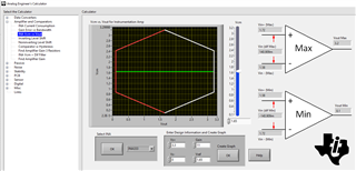
The image below is the linear operation within INA333 with the specified gain and output signal. The input signal is undefined currently.

https://www.ti.com/tool/ANALOG-ENGINEER-CALC
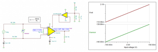
Here is the Tina simulation.

Here are several things to pay attention to:
1. The input signal is required to riding on a fixed Vcm voltage, say 1.65Vdc or similar, since the application is using single supply rail of 3.3Vdc.
2. Vref pin5 is required to be connected to a low impedance source (with sourcing/sinking capable node). The simulation is using OPA2333 to accomplish this. Other stable references are possible including bandgap voltage source (e.g. REF35 or similar).
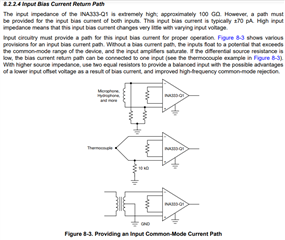
3. If the input signal is floating or lack of input bias current return path to GND, then please read the following section in the datasheet.

4. With Gain = 11V/V and optimized the input and output voltage swings, the input differential voltage range is approx. ±140mV. The INA333's BW is slightly below 35kHz, which is likely acceptable for the EEG like application.

5. You may implement additional differential and common mode filter at the input, if the application is required, see the link below.
If you have other questions, please let us know.
Best,
Raymond
Since a silver electrode is used, an impedance of around 5~20 kΩ is expected. Given that we're dealing with EEG signals, we anticipate an input signal in the range of tens to hundreds of millivolts. It might be beneficial to use 2 to 3 OP-AMPs (one for each electrode), so I will investigate this further.
Thank you for the response. I think I need to understand the basic principles a bit more to grasp it fully. I will install the TINA software and perform a simulation. I will review various references to achieve the basic goal of converting two electrode input signals (silver electrodes and EEG signals) into two amplified signals.