This thread has been locked.
If you have a related question, please click the "Ask a related question" button in the top right corner. The newly created question will be automatically linked to this question.
Tool/software:
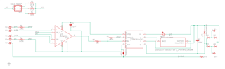
I have a circuit using an INA828 as the front end amplfier to a loadcell and the output 4-20mA current loop driver implemented using an XTR116.
I am very happy with the performance except for one attribute which is surprising given the INA828 is a differential input.
If I touch the loadcell body or the metal plate it is mounted on, the output of the XTR116 changes by 40mV across a 50ohm load so 0.8mA.
Given that bridge input goes into a purely differential input, how is a positive signal being generated?
The bridge impedance is 350ohm so quite low impedance.
Any recommendations?
Hi Craig,
Welcome to E2E!
Could you clarify a few design parameters in your application?
Thank you!
Regards,
Ashley
hello Ashley
V+ 5.0V (from the XTR116)
V- 0V (return on the XTR116)
Differential input signal is from a balanced 340 ohm whetastone bridge loadcell. Excitation voltage 2.5V and loadcell sensitivity 2.0mvV/V
RG is set to 69.8 ohms
Hi Craig,
To clarify, what gain are you trying to set the INA to? What is your desired input and output voltage ranges?
Regards,
Ashley
In this design the gain was set to 717.
Input voltage range up to 1.66mV (2mV/V load cell with 0.83V ecitation)
Output voltage 1.19V
This feeds into the XTR116 via a 10k resistor
The real problem though is that if I touch the loadcell with my hand (without applying any load) there is a very significant jump in output.
How high can the gain be run before there are issues?
I have the ref input connected to the local ground (return on the XTR116), is this a problem? For positive going signals they are going away from the rail of 0V but is it a problem being in this region?
Hi Craig,
Did you measure each section of the system separately to determine where the increase in output is coming from? If pressing on the load cell with your hand is increasing the differential input voltage on the INA, then the output of the INA would scale accordingly.
How high can the gain be run before there are issues?
The gain would not change unless you change the RG resistance. With a gain of 717, the output voltage range limitation of the INA depends on what your Vref and Vcm is. I am not sure what your Vcm on your input is based on your current description, so I recommend using the Analog Engineer's Calculator (ANALOG-ENGINEER-CALC Calculation tool | TI.com) as it will help to determine what your linear operating range is.
I have the ref input connected to the local ground (return on the XTR116), is this a problem?
There is no problem with connected Ref input of the INA to the Iret on the XTR116. Please see this blog here on more information on return currents: (+) 2-Wire 4-20mA Sensor Transmitters: Sensor and Transmitter Current Consumption Limitations (Part 3) - Precision Hub - Archives - TI E2E support forums
Could you clarify though what this jumper is and if it is connected? If so, where does it connect to?
Regards,
Ashley
Hello Ashley,
In a state of rest, the key cct nodes measure as:
-ve diff input: 2.04630
+ve diff input: 2.04627
INA828 output: 0.0086V
When touching loadcell or steel plate it it mounted to (with my finger, no load applied to loadcell) :
-ve diff input: 2.04631
+ve diff input: 2.04627
INA828 output: 0.0129V
All of these voltages are with respect to the V- pin on the INA828 which is connected to the return pin of the XTR116.
All measured with a SIGLENT SDM3065X-SC
The change in differentials is 0.00001, and with a gain of 717 that gives a result of 0.00717 or about 7mV.
So I guess that is where the signal is coming from.....!!!!
Regarding the jumper: This is an optional solder jumper I put in in case connecting this point to the chassis or shield may be useful. It is left OC.
I have tried connecting the body of the loadcell to the DAQ system ground and the issue seems to have gone away.
Not until I looked at these signals with a high enough resolution did the reality become apparent.
Thanks for helping me think through this :-)
Hi Craig,
Happy to help! I will also note that for the Wheatstone bridge load cell, this ground will also have to be connected to the same ground potential as the 2-wire transmitter ground, otherwise you may see issues with the return current loop.
Please let me know if you have further questions.
Thank you!
Regards,
Ashley