This thread has been locked.
If you have a related question, please click the "Ask a related question" button in the top right corner. The newly created question will be automatically linked to this question.
Tool/software:
Hi, professors.
I'm using OPA2227 (OPAx227 series) at single power supply condition. The supply voltage is about +5V to 0V.
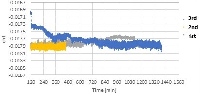
Recently, I noticed the output seems unsteady when the power supply voltage is below +5V (e.g., +4.9V) than when I use above 5V (e.g., +5.1V).
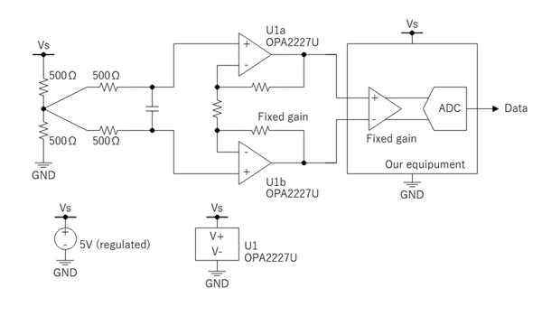
Our circuit is a typical differential amplifier using two opamps included in the same package and some high precision resisters.
The measuring parameter is zero drift characteristics, and the input is biased about +2.5V by the same value resistors, and two amp's +input is shorted.
Temperature condition is +25℃ (const.) using a chamber.
I think different parameter is just the supply voltage.
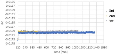
Actually, under investigation, output is very clear and almost no drift when using +5.1V power supply.
Do you know the reason of this problem or the true recommended operating conditions?
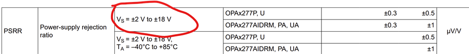
I thought I should use over +5V power supply on OPAx227 series.
Best regards,
Hello,
The power supply can be 4V to 36 V on a single supply. See below.
The input common mode voltage range is 2V inside each supply rail for linear operation. The common mode range for linear operation is circled below and these are the min and max points. Going outside of these boundaries can lead to unexpected results. I would double check that the common mode voltage is set to 2V below the positive rail. Because the linear operation of the device is limited to the common mode range shown below I would recommend operating at the higher supply voltage that is working for you. It will just make it easier to achieve the linear operation point of the device.
I hope this information is helpful. Let me know if I can be of further assistance.
Best Regards,
Chris Featherstone
Hello, Mr. Chris.
In this case, the single supply voltage is greater than 4V so it doesn't be a problem.
Also, the recommended input common mode voltage range is 2V to 3V when using Vs=5V.
Section 6.7 Electrical Characteristics is measured by Vs=±5V to ±15V so I guess those fundamental performance are not shown.
Best Regards,
Kazuyuki Miyashita
Kazuyuki,
Chris is on vacation, so I will help for the time being.
Best regards, Art
Dear Mr. Art,
First of all, I regret my mystakes of part number. I was going to discussing about OPAx227 series.
I changed the part number of this forum.
1. I'm using OPA2227.
2. The supply voltage is +5V single supply generated by a regulated power supply.
3. Here is our circuit.
Unfortunately, due to including technical the information, I'm not able to provide all of it here.
The ADC data rate is 1 sps and using a 0.1 Hz digital lowpass filter.
There two inputs are connected to Vs / 2 so these outputs should have few drift when environment is kept to constant temperature.
This is sampled data when Vs=5.1V. The vertical axis of the graph is normalized to 5V.
I think data is very stable.
However, the measured data by Vs=4.9V seems a bit unstable and noisy.
I tested this experiment with the same 10 circuits under the same conditions, and they behaved all similarly.
In fact, the problem is still under investigation and may be occurring in our circuit or enviroment.
I'm going to investigate to isolate the problem later (e.g., measuring the indipendent drift of out equipment).
Best regards,
Kazuyuki Miyashita
Kazuyuki,
best regards, Art
Dear Art,
Thank you for your opinion.
I'll do more research later and share if I found issues.
Best regards,
Kazuyuki Miyashita