- Ask a related questionWhat is a related question?A related question is a question created from another question. When the related question is created, it will be automatically linked to the original question.
Tool/software:
Hi Sir / madam,
We have one design with LM12C in which we are replacing the LM12C amplifier with OPA549S.
LM12C is used as current drive, also having configuration of current drive as servo driver, So there are 2 of the LM12C are used as shown in below snap.

And

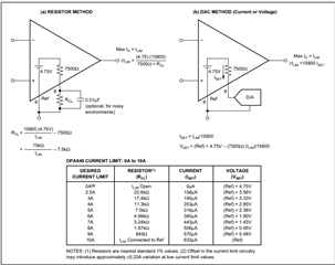
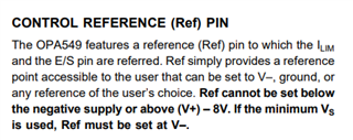
Now, as if we are replacing LM12C with OPA549S, then we have one current limit pin and it is mentioned in the datasheet that the current on I_limit pin varies as per output current. So can we directly replace LM12C with OPA549S with same electrical configurations for Servo drive and current drive ? Or we need to use I_lim as additional feedback input to the feedback path , in place of the feedback from the Series resistor (R6) in output ?
Regards,
Ankit Vyas