This thread has been locked.
If you have a related question, please click the "Ask a related question" button in the top right corner. The newly created question will be automatically linked to this question.
Hello,
For our new product we need to measure inductivity and DC resistance of a fairly fragile device that can only stand 50-70 mV applied across it for a second or so. The input we have is a 12-bit ADC, and the circuit has to be single-supply (5V). Solution we have now is to first, measure DC voltage drop across device, and then measure AC drop at 1 kHz. Here's what I came up with:
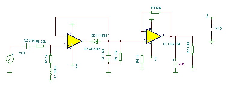
This is AC configuration. R2 is there instead of ADC input.
It simulates well but doesn't really work on the bench, peaking quite wildly. This results in major non-linearity and general unpredictability of output. My guess is that op amps don't really like capacitive loading and inductive sources.
Can anyone help either make this usable or offer an alternative path? Thank you very much!
Alexey
I have two recommendations. First, you are correct that connecting a capacitance directly to the output of the amplifier is likely causing problems. Below is a link to an app-note that shows a peak detector that doesn't have this issue (see bottom of page 18). This app note has a lot of good circuits that may be useful as well.
http://www.ti.com/lit/an/snla140a/snla140a.pdf
The second thing to mention is that your signal is very near the negative supply (gnd in this case). The amplifier you have selected is a “rail-to-rail” amplifier, so you can drive close to the supplies with this device. However, you may be too close. Keep in mind that you have input and output limitations. For this amplifier the output needs to be 20mV above ground to operate. Generally when doing single supply applications it is advised to create a virtual ground. The virtual ground is half way between the supplies (2.5V in your case). All the op-amp grounds are referenced to the virtual ground and the device acts like a dual supply configuration. See the link below for additional info.
http://www.ti.com/lit/ml/sloa076/sloa076.pdf
I hope this helps.
Art
Art, just to report back -- I've breadboarded the peak detector on p.18 and it rings and overshoots just as enthusiastically as the simpler one :)
But adding a buffer before peak detector and recalculating bias for the whole thing according to the second document you linked did solve the problem very well. Thank you!
Hello Alexey,
We are very glad that this worked for you. To help share information in our community would you mind posting a schematic of your working solution?
Thanks!
Collin Wells
Precision Linear