This thread has been locked.

If you have a related question, please click the "Ask a related question" button in the top right corner. The newly created question will be automatically linked to this question.

AC coupled photodiode amplifier: differences on 2 different circuits

Hi,

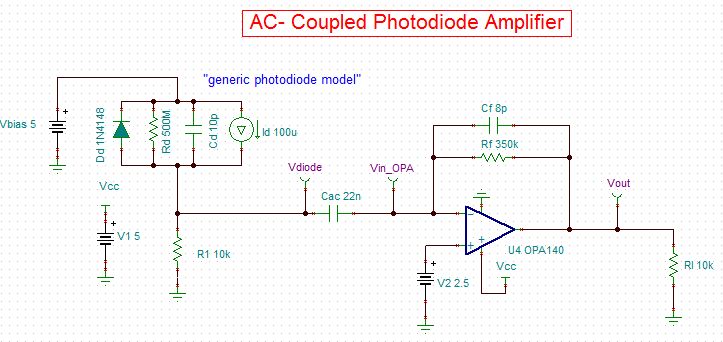
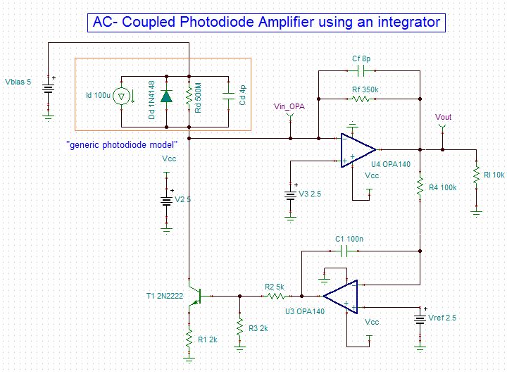
  I have designed 2 different circuits that amplifies an AC signal superimposed to a large DC signal coming from a photodiode (AC signal coming from an I.R LED + DC signal coming from the sun).

In the AC coupled circuit the photodiode is always reverse biased because 10k x Idiode_dc < Vbias thus the circuits seem to have similar behaviour and I'm wondering why the circuit with the integrator is usually preferred ?

Thanks for the feedback

Gabriele


  • Gabriele,

    You are correct that the first circuit keeps the photodiode reverse biased up to 0.5mA DC photodiode current. Throughout the range from zero current to 0.5mA, however, the reverse bias is varying. This may be undesirable in critical applications.

    I believe that the presence of R1 at the summing junction will increase the noise gain of the circuit throughout a frequency range. This may be a possible disadvantage.

    Without detailed analysis, I believe that both circuits have merit. The first circuit is less complex and may be entirely adequate for many applications. To be honest, I made a quick trial design of the second circuit using TINA to answer a forum question. It was intended as a suggestion. I have never fully tested or optimized the circuit. It has reappeared in several later forum postings as community members have had questions on its operation. The fact that it has been repeated in multiple postings should not imply that is the preferred or best solution. It's one possible approach.

    Regards, Bruce.

  • Hi Guys,

    I have same circuit(on Top), Everything works well indoor and on shades.

    But when if the PD is facing the SUN its not working. The PD is saturated current flowing is 2.5mA-3mA.

    Any solution or modification on the circuit?

    Thanks,

    Jay

  • Hi,

      if you are using the 1st circuit (AC coupled with the capacitor) and the photodiode is generating 3mA the voltage on R1 "is"10K x 3mA = 30V : the photodiode is forward biased.

    Try to simulate if with TINA and/or reduce R1

    Kind regards

    Gabriele