This thread has been locked.

If you have a related question, please click the "Ask a related question" button in the top right corner. The newly created question will be automatically linked to this question.

TLC2274A in low side current sense application

Other Parts Discussed in Thread: OPA188

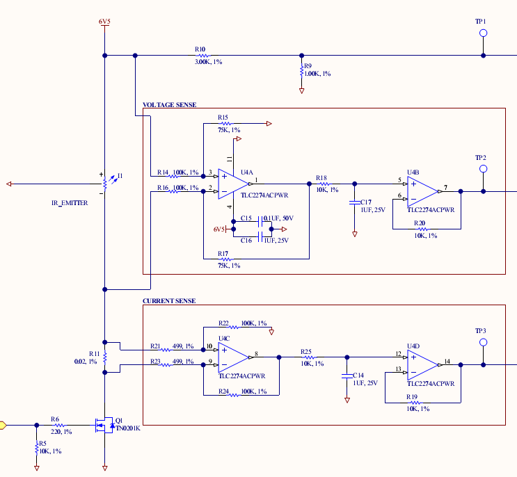
I am using part of this quad amplifier as a differential amplifier in a low side current sense application.  The circuit in question is within the red box labeled "current sense".  The voltage sense circuit functions properly, so the power and ground is fine.

 To test the circuit I took out the MOSFET and placed a pot between the sense resistor and ground.  At 0 ohms, the output of U4C is about 500mV and the current across the pot is about 102mA.  I then increase the resistance, and both the output of U4C and the current continue to decrease as then should.  The unexpected behavior is around 30mA and the voltage on U4C is about 200mV.  As I continue to increase the resistance, the current will continue to decrease, however the amplifier output begins to increase to about 330mV.  At that point the voltage will "runaway" and increase on it's own to the positive supply rail, without changing the resistance of the pot.

I can't seem to figure out why this would be happening.  Is there a design flaw?

Thanks

  • Mark,

    It appears that your test approach may be flawed.

    The output voltage is of U4C is determined not only by the current flowing in R11 (a pot in your test) but also the the resistance of R11. As you you increase the resistance of R11 the current decreases but the voltage it creates on R11 may increase due to its increasing value. It's a nonlinear effect due to the fixed voltage source (6V5) and the non-linear impedance of the IR_emitter. Imagine, in the limiting case, R11 goes to infinite resistance (zero current) but the voltage on your difference amp is equal to 6V5.

    Regards, Bruce.

  • Bruce,

    Thanks for the quick reply.  The pot in this case is not replacing R11, it is replacing Q1, or to say it is between the bottom side of R11 and ground.  Therefore R11 is always constant. When you open the pot up, I would expect the output of U4C to goto zero.  However it will ramp up to the positive supply rail.  It does not behave like this when I change the circuit to have unity gain.

    After further investigation, I think what could be happening is R11 is too low of a value, causing the difference of the inputs to be below the offset voltage of this particular amplifier. Does this sound feasible?

    Cheers, Mark

  • Mark,

    Okay, I understand. Sorry I misinterpreted.

    You are probably exceeding the common-mode range of the op amp. The TLV2274 does not have a rail to rail input stage. If the non-inverting input voltage of the op amp rises much above 1.5V from the positive rail voltage (5V, in your case), it will cease to operate as a linear amplifier.

    It appears that in normal operation you are probably okay but with this testing approach it creates a problem. If you move the pot to above R11, you are likely to get better results.

    Regards, Bruce.

  • Bruce,

    I don't think that is the case because my positive supply rail is 6.5V, which the non-inverting input voltage will never exceed.  This issue is seen in the circuit as shown in the picture, even without the testing pot.  When the MOSFET (Q1) is off, I get about 500mV out of the opamp.  That calculation leads to 124mA, which is about what I would expect (the load is about 50 ohms).  When Q1 turns on, you will see the output of the amp ramp up from 500mV to the supply rail (6.5V) over the period of 5-20 seconds.

    I was using the pot in an effort to see exactly at what point that happened.

    Cheers, Mark

  • Mark,

    In your case, the common-mode voltage cannot exceed 5V, 1.5V below the positive rail voltage. If the FET can be turned completely off (zero current) and you need accurate current measurement, you will need an op amp with rail-to-rail input.

    With a rail-to-rail input op amp, you will still have a lower limit to the output voltage of U4C. The output will limit to perhaps 20 to 30mV from ground due to the output voltage swing limitation of the op amp.

    Regards, Bruce.

  • Thanks Bruce!  That makes perfect sense.  The issue was happening when the input was right around 5V, as you said.  Is there any specific rail-to-rail input op amp you would recommend for this?

    As a followup, do you think this is a decent implementation to accomplish my current sense goals, or would you have a different suggestion? 

    Thanks, Mark

  • Mark,

    You apparently have a full-scale voltage on the shunt R11 of about 25mV, or so. I'm a bit concerned about the influence of offset voltage. Your original selection had a max offset voltage of 2.5mV, a 10% error relative to full scale. Can you tolerate this?

    I would recommend a chopper op amp for this (OPA188) but it, too, does not have a rail-to-rail  input voltage. Seems like you could move R11 to the source of Q1. This would avoid the whole common-mode issue. Then you could use a chopper op amp for much lower offset voltage.

    Regards, Bruce.

  • I do not seem to have these same problems with the voltage sense part of the circuit.  The only thing that is different is the gain, which is in this case, 0.75.  When the FET is off, the inputs are around the supply voltage.  Is this somehow related to the common-mode input voltages?  Is it safe to keep using the amplifier like this?

  • Mark,

    The common-mode voltage of the upper op amp is divided down to 6.5V*75k/(75k+100k) = 2.8V. This is easily within the common-mode range of the op amp.

    Did you move R11 to the source of Q1?  Did you consider the offset voltage issue in the current measurement circuit?

    Regards, Bruce.