This thread has been locked.

If you have a related question, please click the "Ask a related question" button in the top right corner. The newly created question will be automatically linked to this question.

UAF42 active filter, variation

Other Parts Discussed in Thread: UAF42

Hi,


I have question regarding the variation of UAF42 BPF characteristics from a customer.


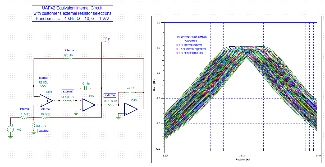
They set the center frequency a few KHz and tried to get x1.0 gain at that center frequency with UAF42.

 They assumed the variation of gain is under 3,4% as Max and have observed the smaller variation with almost device.

However, they found a attenuation ratio of the gain was under 9% with a UAF42 and assumed that is abnormal performance as UAF42.


Regarding the resistor value for example R2, R4 variation should be under 1%.

Thus, customer could not understand the reason that the over 9% gain attenuation was observed. 


Would it be possible for you to tell the reason of the gain attenuation that you can expect?

Do you think it is possible the inside "C1 1000pF variation" and inside "amp characteristics variation" made the attenuation ?

Or is it possible the variation of center frequency ( cut off frequency ) of BPF is the reason for the gain attenuation ?

Best Regards,

Charlie Maehira/ Japan Disty

  • Hi, teams


    Would it be possible for you to give the response to this ?
    I would appreciate it if you could reply promptly.

    Best  Regards,

    Charlie Maehira

  • Hi Charlie,

    I was away on vacation last week and I am now working through inquiries of this nature.

    The specifics of the band-pass filter that the customer is attempting to synthesize are needed; center frequency, bandwidth, gain, response type (Butterworth, Chebyshev,..), etc. In fact, the filter schematic showing supply levels, input signal source and output load, resistor and capacitor values are needed to fully assess the expected filter performance.

    Regards, Thomas

    PA - Linear Applications Engineering

  • Hi, Thomas

    Thank you very much for the reply.

    I attached the schematic that has the necessary parameter by the image as below.
    If you need additional information , please let me know.

    Best Regards,

    Charlie Maehira

  • Hi Charlie,

    The information provides some of what I need, but not all. As I mentioned previously, I need to know what the performance goals for the band-pass filter are; gain, center frequency, bandwidth, Q, response type, etc. It would also be helpful to have the input source and output loading information.

    I am having a little difficulty seeing the RF1 and RF2 resistor values. It looks to be 39.7 k, but I need to know for certain their values.

    Thanks, Thomas

    PA - Linear Applications Engineering

  • Hi Charlie,

    If the RF1 and RF2 are 39.7 k-ohm, the UAF42 band-pass filter would have the following response characteristics (approximately):

    fc = 4 kHz

    fL = 3.818 kHz, fH = 4.209 kHz,  BW-3 dB = 391 Hz

    Q = fc / BW-3 dB = 10.2

    G = 1.00 V/V

    The response appears to be Butterworth.

    Can you confirm these are the filter response requirements? I plan to run some Monte Carlo analyses based on component tolerance variations and will do so once I know that I am on the right track.

    Regards, Thomas

    PA - Linear Applications Engineering

  • Hi, Thomas


    I got the response from customer .

    The parameter that you mentioned in E2E is filter response requirements of them.

    And we have the several questions regarding the simulation/analysis.

    Would you tell us what "component tolerance variations" is ?
    For example, are these variation by resistor, capacitor , transistor parameter inside IC?
    And if you have the information of the variation source that you will use with Monte Carlo analyses , please let us know .
    ( Does not random number simulation need  the source information ?)

    Best Regards,Charlie Maehira

  • Hello Charlie,

    The UAF42 component tolerances are provided in the data sheet. The internal 50 k resistor tolerance is typically within +/-0.5 %, with a maximum of +/-1 %. The internal capacitors are listed as 1000 pF, +/-0.5 % tolerance.

    I performed Monte Carlo and Worst Case analyses using TINA Spice. The internal operational amplifiers were presumed ideal which allows just the component tolerances and their effect on gain, frequency, etc. to be evaluated. Using the tolerances specified above for the internal components and +/-1 % tolerance for the external resistors, the worst case gain deviation from the ideal 1 V/V (0 dB) was less than +/-0.5 dB. When only the internal components and their tolerance variances are evaluated this is more on the order of +/-0.3 dB. +/-0.5 dB is about a +/-5.6 % gain variance from ideal, and +/-0.3 dB is about a +/-3.5 % gain variance from ideal. Neither is as high as the -9 % the customer is reporting.

    You can see the TINA Spice circuit and the resulting worst case analysis ac response plot for the customer's circuit below. I've also attached the image file for better viewing.

    I have considered the internal operational amplifiers, but something would have to be grossly wrong with their performance to contribute a gain error of the magnitude reported by the customer. They are tested in production and shouldn't be a problem.

    My simulations assumed a source impedance of zero, but if it isn't zero that can affect the voltage gain. Another possibility is the external components have a wider tolerance than expected. And there is always the possibility that something is not quite right with the UAF42 devices they have received; however, if they are genuine UAF42 product they have received the full production testing.

    Regards, Thomas

    PA - Linear Applications Engineering


  • Hi, Thomas

    Thank you very much for the simulation result and description in detail.
    We will provide these information to the customer after considering how we should explain it.
    We will ask afresh if we have the additional question from customer.

    Best Regards/Charlie Maehira