This thread has been locked.

If you have a related question, please click the "Ask a related question" button in the top right corner. The newly created question will be automatically linked to this question.

Signal and bias levels suitable for LMH6882

Other Parts Discussed in Thread: LMH6882, THS4502, TINA-TI

Hi,

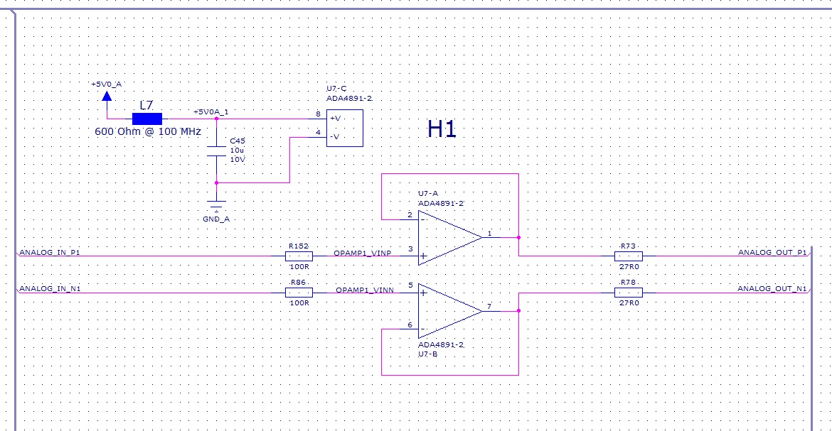
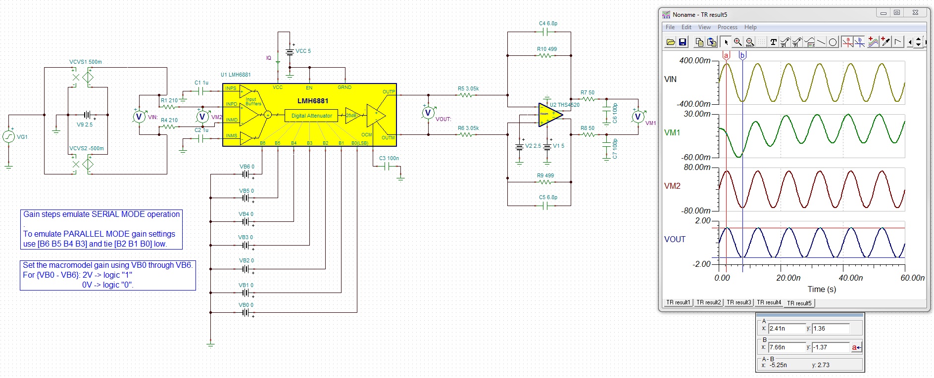
We are currently debugging a new ADC-based design and we are using an LMH6882 variable gain amplifier to fine-tune the incoming analogue signal. However we are finding that the output amplitude from the LMH6882 is far lower than what we have simulated. I've attached a PDF of the current circuit.


Could someone comment on how we've biased and set the feedback for this circuit?

Thanks,

Eoin

4477.13x13_ADC_20140429_amplifier.pdf

  • Hi Eoin,

    The input common mode of LMH6882 is internally self biased to 2.5V and the output common mode is controlled by the Vocm pin which you have it correct in the schematic. The gain of the LMH6882 is set by the internal Rg and Rf (feedback resistors), so there is no need of external feedback circuit.

    I am curious to know about the R14-R17 resistors which would act as increasing the Rg and bring the gain of the LMH6882 down or having a higher voltage drop across the R14-R17 resistors.

    Do you know what is the source/sensor impedance?

    Best Regards,

    Rohit

  • Hi Rohit,

    Many thanks for replying.

    We intentionally limit the gain of the LMH6882. We only want to be able to adjust the overall gain of the circuit by about 10 to 20%. It is replicated in 7 parallel channels and is there to make sure that each channel has the same gain and offset.

    The sensor output is buffered through a voltage follower and a 27R series resistor:

    Thanks,

    Eoin

  • Hi Eoin,

    Ok, thanks.

    Do you know what is the output for the LMH6882 targeted for a 1500mV-2200mVppd input?

    Do you know what is the gain of the LMH6882 being set and is it possible to probe at the input and output of LMH6882 on an oscilloscope?

    Best Regards,

    Rohit


  • Hi Rohit,

    I have the following figures from a simulation.

    The sensor input was setup to produce a 2V peak to peak differential - 1300mV-2300mV input.

    With maximum gain set (0d), the simulation indicates that the LMH6882 should output 960-4040mV peak to peak. At minimum gain, we expect 2080-2920mV.

    At the output of the differential amplifier (i.e. the overall output), we expect to see 350-1650mV at max gain and 520-1480 at min gain.

    In practice, the maximum input we see from the sensor is 1400-2200mV. At maximum gain, LMH6882 output is 2260-2570mV and overall output is 560-1480mV.

    -Eoin

  • Hi Eoin,

    What simulator are you using for simulating your circuit? I have attached a TINA-TI simulation of your circuit only associated with the LMH6882 and have partly included the THS4502.

    I have attached a simulation with 1500mV - 2200mV  that you have in the pdf file sent which I am assuming to be 700mVppd centered around 1.85V DC common mode as the input to the LMH6882 before the 210ohm resistor. If I do it this way, I get 2.73Vppd at the output of LMH6882 for max gain.

    One thing I wanted clarification was that the 1300mV-2300mV input you have mentioned is actually 1Vppd, correct? centered around 1.8V DC common mode as the input to the LMH6882 before the 210ohm resistor? Also, what is the range of input frequency that we are dealing with?

     6165.LMH6882_Eoin_gainissue.TSC

    Best Regards,

    Rohit

  • Hi Eoin,

    I am not able to understand why the output of LMH6882 would only be 2260-2570mV for a 1400-2200mV input signal unless the LMH6882 is set to minimum gain.

    Is it possible for you to share oscilloscope plots of inputs and outputs to the LMH6882? Also, what is the supply current being read for the LMH6882?

    Best Regards,

    Rohit