This thread has been locked.

If you have a related question, please click the "Ask a related question" button in the top right corner. The newly created question will be automatically linked to this question.

0-10V to 4-20mA interface, request industry standard suggestions

Other Parts Discussed in Thread: XTR110, XTR111, TIPD153, XTR106

Hello everyone.

I have not been able to find any TI documents to help with this question. If there are some available, please advise, thanks.

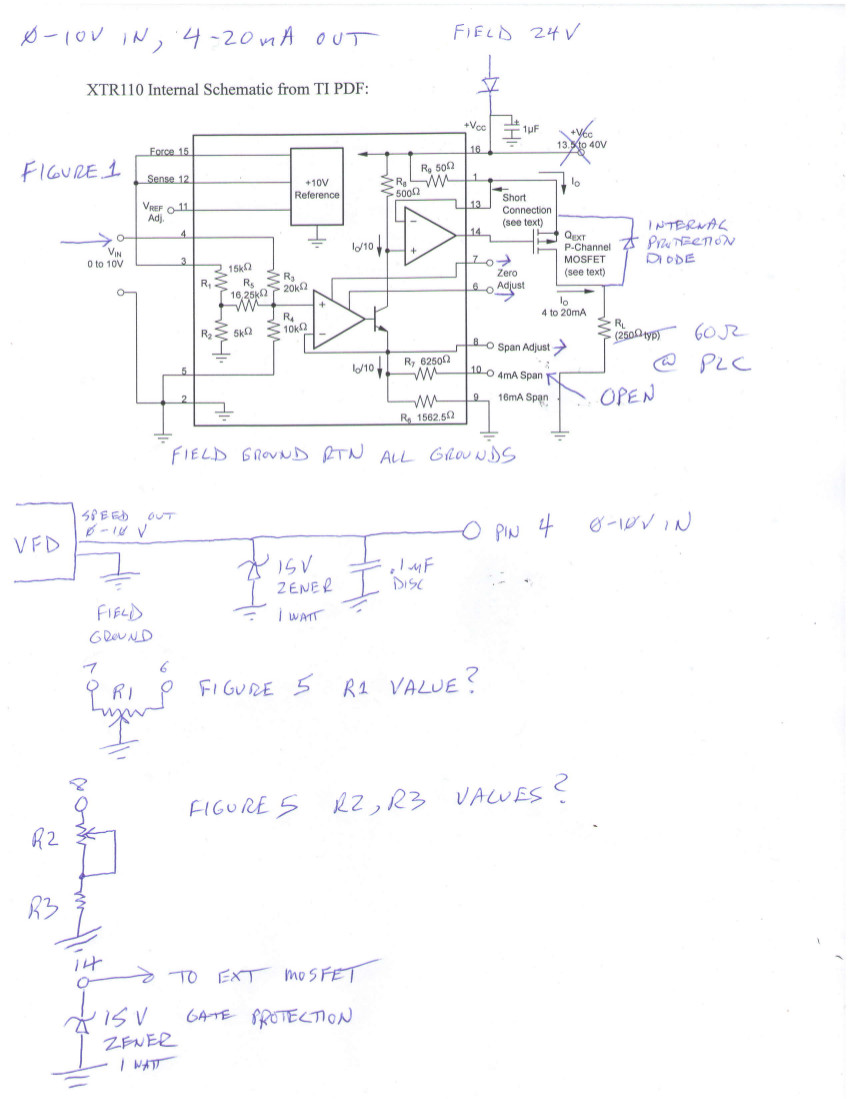
I am requesting XTR110 industry standard suggestions for a 0-10V 4-20mA interface from an Eaton VFD analog output to an Allen Bradley PLC input using this chip. I had previously implemented it using discreet components but was dissatisfied with the linearity and thermal stability. Although the XTR110 replaces almost all of the circuitry I had designed, I am concerned with industry standard implementation and protection of the device in student workstations.

I am including the basic circuit with the following questions:

Recommended parts for through hole implementation:

Clamp diode to protect A1 from -.5V at pin 4

A suitable external mosfet that is not in a to-92 package (I can not find this from available recommended parts)

A suggestion for protection of the external mosfet drain which is wired directly to the PLC analog input card

Please take a look at my simple implementation and make suggestions.

Thank you very much.

  • Hello,

    I've provided answers to your questions below:

    Clamp diode to protect A1 from -.5V at pin 4:
    -consider the BAT54 Schottkey diode.

    A suitable external mosfet that is not in a to-92 package (I can not find this from available recommended parts)
    -The XTR111 is a similar/newer product than the XTR110 and lists the following as recommended PMOS devices:  BSP170P, 2SJ326-Z, NTF2955, TP2510

    A suggestion for protection of the external mosfet drain which is wired directly to the PLC analog input card:
    Reference Design, TIPD153 ( http://www.ti.com/tool/tipd153 ) shows a 3-wire 4-20mA output protection scheme that passes the IEC61000-4-X series of tests.  Consider using something similar if you're worried about protecting the output of the XTR110.

    Values for R1 - R4 are shown in Figure 6 for a 4-20mA output with a 0-10V input.

    I do not recommend the circuitry that you've shown for protection of pin 14 (Gate Drive).  Since the XTR110 drives a PMOS device, the Gate Drive output must be able to swing to the positive supply which will not be possible with the 15V Zener placed on pin 14.  If you're worried about protecting pin 14, consider placing clamp-to-rail diodes (similar to what's shown in TIPD153) on the output. 

  • Thank you for your suggestions, and the speed of your response, Colin. I have investigated them and they seem complete, but due to an emergency I have not been able to follow up yet.

    Derek

  • Hi Colin
    I am still having trouble finding a through hole pmos enhancement mode device that has a better package than to-92, and corresponds to the recommended devices.
    Also, regarding the pin 14 protection, my field voltage is 24V single ended, not +- 15v, and most Vgs values are +-20v. The documentation for xtr110 suggested a 12v zener in that situation if I understand correctly.
    I hope to get a mosfet with Vgs of 30v or better for that reason.
    Similarly, the diagram for the protection for the drain in TIPD153 is using a +- 15v supply if I am looking at the right diagram, and I have a single +24v supply.
    Thanks
    Derek
  • Hi Derek,

    As long as you're not violating the absolute maximum ratings of the MOSFET, basically any PMOS will work so we recommend that you select one in the package you're interested in using and try it out.

    Thanks for clarifying your goals for the pin 14 protection.  The zener must be connected between the gate and source of the PMOS device, not from the gate to GND.  Therefore place the anode on pins 1/13 and place the cathode on pin 14 to limit the maximum gate-to-source voltage that the PMOS will need to overcome. 

    TIPD153 shows a bipolar protection scheme, but by connecing the -15V clamp diode to GND and replacing the bidirectional TVS with a unidirectional TVS you can convert it to a unipolar protection scheme.


  • Hi Colin, yes I got confused and will use the zener from the source at +24v approximately to the gate, thanks.

    Since this is being built for students, I am concerned about what would happen if the 0-10v pin 4 input is accidentally wired to +24V field voltage. It doesn't look like it would damage the chip, but would that cause a large current through the external mosfet? If I put a series resistor, say 220 ohm .5 W with a 1W 12V zener to ground behind it ahead of pin 4, it looks like the ratio of 220 to 20,000 for the input resistance would give me a 1.1% error in voltage input to the A1 opamp.

    24V field to 0-10V in-------220ohm----|--pin4------20k-----+ inputA1opamp...............extPmos
    ...........................................................|............................................................................ |
    ...................................................12V zener.........................................................overcurrent to PLC?
    ...........................................................|
    ...........................................................Ground

    Is there a better way to safeguard accidental hookup of 24 V there, or is it not an important issue?

    I am also wondering about leakage current through the zener during normal operation in this high impedance circuit introducing an error.

    Thanks

    Derek

  • Hi Colin

    I am also converting the input from a 5K pot at the student station to a 4-20mA output to the PLC 4-20mA input card.

    I had planned to simply use the internal 10v reference from the xtr110 to one end of the pot, ground the other end, and connect the wiper to pin 4. Of course, I would need to include the protections from mis-wiring I mentioned before (24V field or ground connected to the 10V reference would destroy the chip I think).

    I also have an xtr106, and could use a resistance bridge. It seems it would be a lot simpler to just use the xtr110 as I mentioned above, but I would like to know about precision issues, and get your advice on best practice. If you think the bridge is the best idea, could you refer me to a good example for implementation of that?

    Thank you for all your help

    Derek

  • Hello Derek,

    As long as the input voltage to pin 4 doesn't exceed the +VCC voltage, then it will not damage the device.  The output current be very large though and may damage the PLC input module you're connecting it to.  The circuit you've recommended would work but would cause gain errors as you've noted.  Consider implementing a standard output current limit circuit such as one of the circuits shown in the XTR111 datasheet.  I've copied the circuits below: