
- Ask a related questionWhat is a related question?A related question is a question created from another question. When the related question is created, it will be automatically linked to the original question.
Hi,
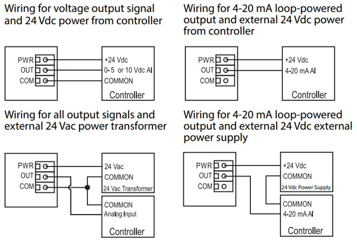
i'm developing a sensor that should have 4-20mA and 0-10V output, jumper selectable.
The sensor has 3 connections, PWR, OUT and COM.
For most applications it should work with 4mA, and could use 2 wire connection (PWR and OUT). It will have an option with displays and relays, that would consume more than 4mA, so it would have to insert COM line for extra current.
It could be powered with AC, and in this case should connect COM line.
Basically the connection are those:
Usually i would simulate on LTspice, but i haven't find the model for XTR115, and i'm very uncomfortable developing those analogical and not usual ground separation, so i need some help with this.
I started with the circuit below.

GND - Basic functionality of the sensor, powered by 5V XT115.
COM-GND - Would return the current from optional extra functionalities, Display, relays, etc, powered by other sources (LM317 in example)
The jumper should pass 1A or 2A to A, same for B and C.
"A" should make the current pass trough the resistor, making voltage output.
"B" line should tell uC that it's Voltage selected, changing the range of the DAC-OUT1.
"C" - Nothing yet.
Some doubts:
Does R16 work for that desirable Voltage output?
Does the ground separations are correct?
Will the circuit work with the AC option?


