This thread has been locked.
If you have a related question, please click the "Ask a related question" button in the top right corner. The newly created question will be automatically linked to this question.
Hi,
I'm trying to use the LOG114 to measure negative currents in the range of 100p to 10uA.
First a description of the application: We are using a microchannel plate (MCP) to collect ions. The output of the MCP is a stream of electrons on the anode that need to be measured (See picture for basic orientation)
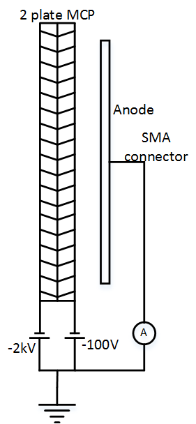
I'm trying to use the LOG114 in place of the ammeter for measuring this electron current. To achieve this objective, I tried connecting the anode to the LOG114 through the current inverter circuit as seen in Fig 7 of the datasheet . See TINA simulation circuit below:
While the simulation shows a perfect transfer function as it is expected at the output, on actual testing, the results are erratic and do not follow a log function with jumps in the voltage output.
When tested individually, the current inversion section and the log-amp section work as expected. Even when connected together, if there is an ammeter placed between inversion circuit out and I1 of the LOG114, the ammeter reads the correct positive current. However, the output voltage of the log-amp doesn't represent this current. The laboratory tests are being conducted with a precision current source in place of the MCP.
Any ideas on how to proceed at this stage?
Thanks,
Vidur
Hello Vidur,
You are working in the realm of very small currents where leakage currents can easily disturb the performance of the circuit. There are two things that are crucial to obtaining maximum performance; minimizing the leakage currents and maximizing circuit cleanliness. Are you using the the LM394 for QA and QB? They are a matched pair of bipolar transistors that should have very similar leakage currents and matched base-emitter voltage. The LM394 is obsolete and not easily obtained. You might try a DMMT5551, or LS312, as a replacement.
The diodes need to have low leakage current as well. Do a web search on low-leakage, small-signal diodes. The BAS116H is a possibility:
http://www.nxp.com/documents/data_sheet/BAS116H.pdf
Any remaining solder flux on boards can provide paths for leakage currents. This can be a real problem for low current circuit operation. Cleaning a PC board with alcohol almost never results in a board that is clean enough for a low current environment. We clean our boards using a DI water bath in an ultrasonic cleaner. Then, the cleaned baords are placed in a heated oven at temperatures up to about 70 C, for 15 to 30 minutes. Any moisture needs to be driven off.
Note that as the circuit temperature increases the leakage currents associated with transistor junctions increase too. Leakage currents about double for every ten degree C increase in temperature.
I hope this information helps you move your project in the right direction.
Regards, Thomas
PA - Linear Applications Engineering