This thread has been locked.
If you have a related question, please click the "Ask a related question" button in the top right corner. The newly created question will be automatically linked to this question.
hi
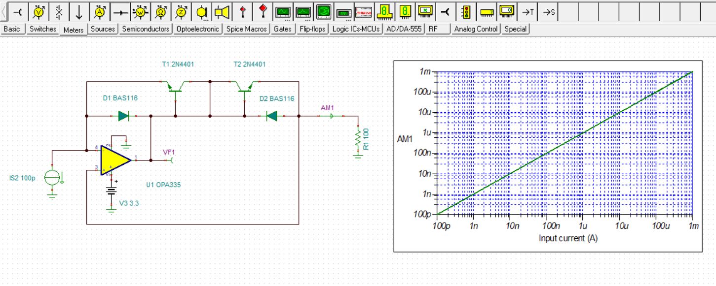
Using negative bias, we want to drive log114.
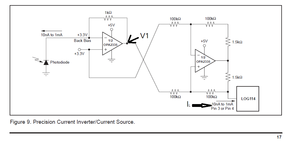
I have found a circuit that can use negative bias in the datasheet.
There are questions in this circuit.
1. I want to know the mathematical formula between il and v1.
2. I would like to know the induction process of the mathematical formulas.
Thanks for your reply.
Hello Hyunwoo,
Actually, I find that keeping the current inverter circuit as simple as possible reduces the sources of error in the circuit. In particular, the Figure 7. "Current Inverter/Current Source" is easiest to apply and can achieve high accuracy. The two other circuits use two-stage designs, requiring more components that can add additional errors over a simpler circuit.
I show below a TINA simulation circuit and results for the Fig. 7 current converter. This current converter is a current mirror and the output current mirrors the input current. The simulation graph shows the output current into a resistor load vs. the applied input current.
The practical mirror circuit should use a precision operational amplifier having low voltage offset, low input-bias current, a common-mode voltage input range that extends to ground, and output swing range that can swing close to ground. The OPA335 shown, or the OPA333 would be good choices.
The diodes used in the circuit should have low leakage current and the BAS116 shown should work well. Even though two identical 2N4401 transistors were used for the simulation, real devices wouldn't likely be matched very closely. There are numerous dual NPN transistor devices available, but some are not well matched. The LM394 shown in Fig. 7 was an extremely well-match NPN transistor pair and was ideal; however, it is now obsolete. One possible replacement is the NST65011MW6. There are other well-matched NPN pair devices available, but their cost is high.
I have attached my TINA circuit should you want to try a simulation.
Regards, Thomas
Precision Amplifiers Applications Engineering