This thread has been locked.

If you have a related question, please click the "Ask a related question" button in the top right corner. The newly created question will be automatically linked to this question.

Problems to measure current with ina284

Other Parts Discussed in Thread: INA284

Hello,

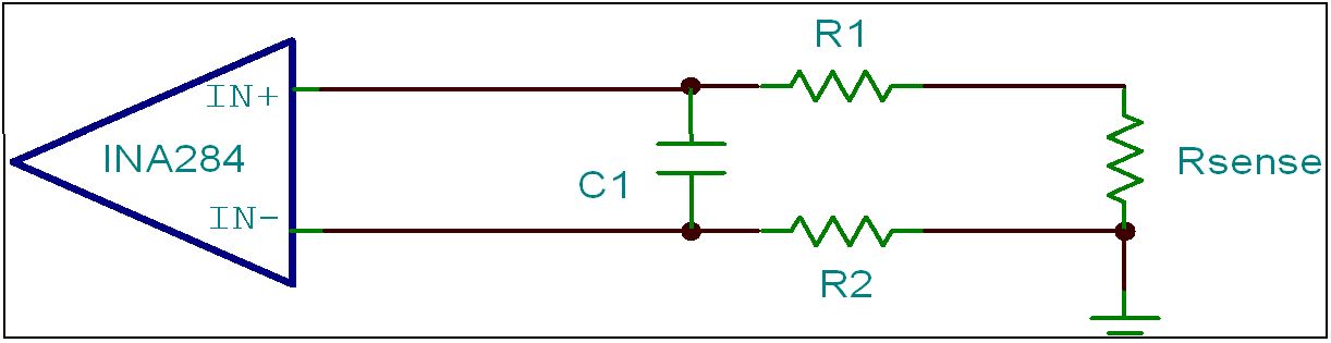
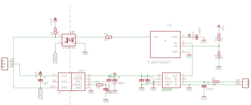
I tried to measure a current throw a shunt with a resistance of 100µOhms. The GND is galanic isolated from the high voltage. The supply voltage is 5V. I would filter some noise out of the measured voltage with a low pass filter. But if the low pass resistor R6 is connected the output voltage is everytime 5V. I think it's because the INA284 has 25µV input current. How I can change the schematic to suppress this effect. When I replace R6 with a short circuit it has a offset of few amperes. The shunt resistor is between P$1 and P$2 on the right connector.

Attached you can find my schematic. If you have other improvements I would be pleased.

Martin

  • Hi Martin,

    The input filtering needs to be modified. If you want to add input filtering to the device you need to add resistors in series with each input. Try connecting 10ohm resistors on BOTH IN+ and IN-. I am not sure what noise are you trying to filter so you need to play around with the values. Also connect a ceramic capacitor between them. See circuit reference below. You could also add RC filter on the output of INA284.

    Hope this helps!

  • Thank you Mayrim! I would use a filter with a frequency of 30Hz. So I should increase the capacitance and decrease the resistance? Today evening I will try it.

    Martin

  • Hi Martin,

    30Hz or 30KHz? For 30HZ you will need a huge cap! It will slow down your system significantly, you will need to wait long time to get valid data. 

    We usually recommend Rs = 10ohms, Cfilter = 1uF (max), this gives you a filter 16kHz. 

    Please share more information about the application so we can provide more inputs.

  • Hello Mayrim,

    now I tried it with 10 Ohms and 10µF. The current measurement should be in a formula student car and should measure the current. If there flows a current of 10A the output should be low. With the second resistor it works better, but there is a non linearity. When I set 10A it should be 0,5V it is 0,58V and at 3A it is 0,25V output.

    Martin