This thread has been locked.
If you have a related question, please click the "Ask a related question" button in the top right corner. The newly created question will be automatically linked to this question.
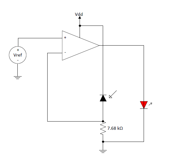
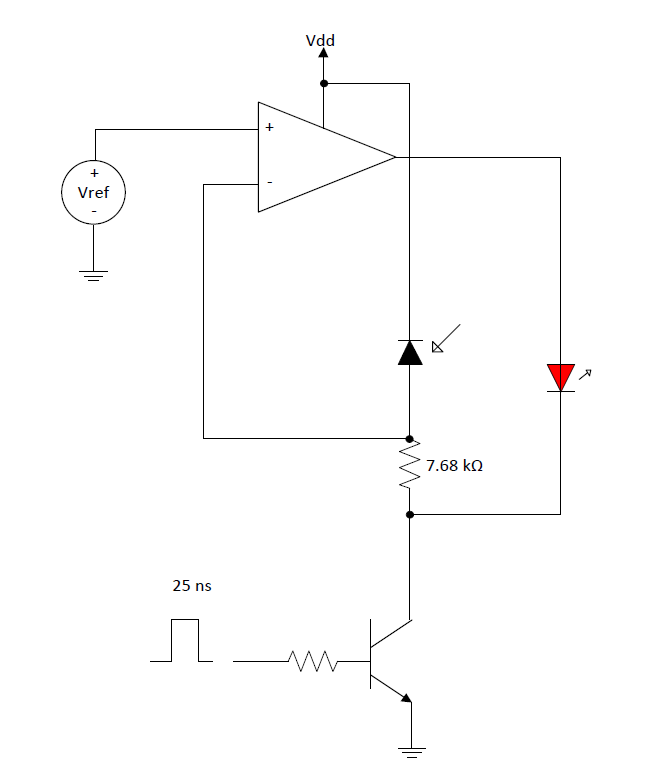
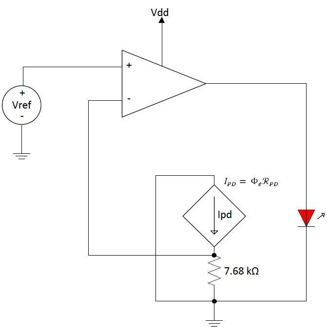
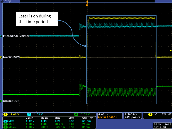
I am working on a design that incorporates an OPA835 to control the current pumped into a semiconductor laser diode. The feedback of the control loop utilizes a Si photodiode that is part of the laser diode packaging (schematic below). When I breadboard this circuit and use a DC reference of 800 mV, the op amp output is oscillating (the oscillation is approximately 1 Vp-p at 6 MHz) when the laser is turned on (the laser appears to be operating correctly). Based on the open loop phase characteristics of this op amp I am wondering how this is happening and what may be done to reduce the instability. When I remove the photodiode from the circuit and replace it with a voltage equal to Vref, the control loop is very stable.
Parameters:
Vdd = 3.6 V
Vref = 800 mV
Laser Diode Forward Voltage Drop = 2.2 V
Laser Diode Current = 12 mA
Photodiode Capacitance = 10-20 pF
Closed Loop Gain = 2.75 (Vref = 0.8 V, Vout = 2.2 V)
-Andrew
Gentlemen,
If I may suggest, the stability issue here is most likely simply due to the phase shift introduced by the feedback, in particular the 10-30 pF photodiode capacitance with 7.68 kOhm load resistor stands out. I don't think you would expect the OPA835 to be stable in a unity gain follower circuit with 7.68 kOhm feedback resistor and a 10-30 pF additional capacitance to ground at the inverting input.
Probably it would be useful to measure the open-loop response from the laser diode drive voltage (with a resistor included in the circuit - this is important so that a reasonable large voltage swing on the opamp output like 1 V or so is used to cover the relevant range of drive currents) through to the photodiode current, and measure the photodiode capacitance, and then create some SPICE model for the current response and see what it takes to stabilize the circuit.
I would guess that a capacitor from the OPA835 output to inverting input, or perhaps an R+C in series with perhaps another smaller C in parallel, will stabilize such a circuit. Without such a direct feedback network though there is way too much gain for stability here.
I hope this comment may help. I do apologize if I am saying anything wrong, I am speaking from experience with similar circuits but of course I haven't done any work on your particular case and much depends on the details of response of the laser diode and photodiode.
If you make this work please post your final circuit as others (myself included) might want to make use of this someday, thanks!
Hi Gerard,
If the loop was closed, then I agree....the loop gain analysis would show additional phase from the noise gain zero added by the 7.68k and 10pF cap. However in this case the amplifier is running open-loop. The only closed-loop system control is optical.
Can you please draw out a TINA schematic on how you would do the loop-gain analysis for this particular setup. I tried but was unable to find a point to close the loop to get the "Beta" feedback factor.
-Samir
hi Samir,
I'm afraid I myself don't have any specific information about the open-loop response of the laser diode and photodiode.
But for the sake of argument assume that the laser diode response is infinitely fast, not true of course. And assume there is no time delay (electrical or optical) involved. And assume the photodiode response (photons -> current) is also infinitely fast (which is maybe a somewhat reasonable approximation).
Then equivalent circuit would look like this
Where Vthreshold is the voltage (applied to the resistor+laser diode) that corresponds to the threshold of lasing, and G is the effective transconductance from laser + resistor driving voltage to photodiode current. I think Andrew can give these things from the datasheets, once the series resistor of the laser diode is picked.
Clearly, this circuit is not going to be stable as such, at least not unless G is very small. It's really no different than having a 7.68k feedback resistor and a 10pF extra capacitance on the inverting input in a unity gain amplifier.
In reality, the laser diode must have some time response that needs consideration too. I think what's needed is to measure the open loop response and then model it (inserting some poles and maybe even time delay between the opamp output and the G device in my circuit above).
My apologies for drawing in LTSpice rather than TINA but it is what I work with here...
Andrew,
In this case the loop is closed around the amplifier. This could be analyzed in 2 scenarios:
1. Transistor OFF - In this case an impedance model of the laser diode will be needed to do the loop gain analysis. We already know the photodiode capacitance. Once these elements are added a loop gain simulation can be done to check stability and phase margin.
2. Transistor ON - The model of the transistor can be included in the loop gain analysis to recheck stability.
-Samir