This thread has been locked.
If you have a related question, please click the "Ask a related question" button in the top right corner. The newly created question will be automatically linked to this question.
Hello,
I am founding lot of problems calculating the phase margin of a circuit.
To measure the phase margin I am using this other circuit, dividing fb(s)/inm(s) at the output.
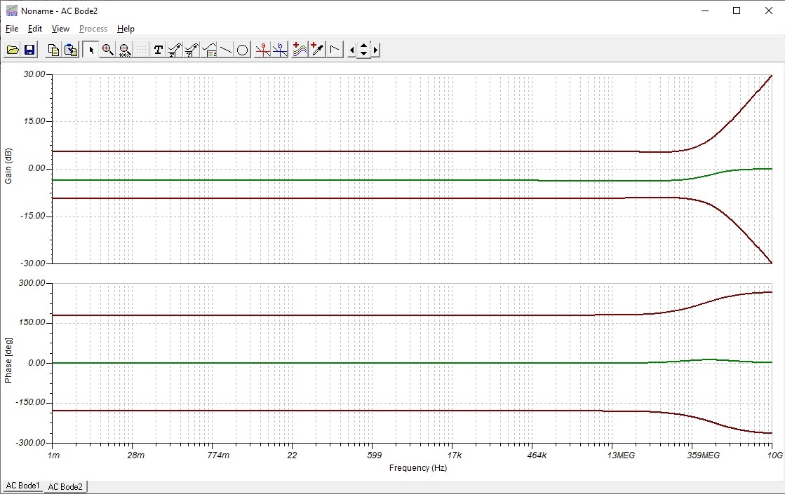
This is what the output look like, with the variable resistor at 20%. Do you have any idea of why it is not working?
Thank you
Hello Javier,
Before trying to do a stability analysis, I have a few questions:
1) Could you clarify the function of the circuit? You state the output is correct, what should you be achieving?
2) Is the poteniometer setting supposed to be fixed or are you trying to vary it using VG1? What setting % do you have it set at?
3) Can you attach your TINA files?
Best,
Hasan Babiker
Hello Hasan,
Thank you for your answer.
1) The circuit is a simple amplifier, with variable gain controlled with the potentiometer and a DC offset.
2) The potentiometer changes the gain of the amplifier
3) I have attached the circuit
Regards
Hello Javier,
Thank you for the clarification. Because you are using the part in a single supply configuration, you will want to reference your circuit to midsupply (2.5V). This way the amplifier is not railing at DC and the amplifier can utilize its full output range. I've modified your stability circuit below:
Where you seem to be getting a phase margin of 83.65 degrees. I would recommend simulating stability as shown in this modified circuit:
Where I am getting a phase margin of 75.64 degrees of phase margin. Note the added resistor and cap (200k and 1.2pF) is the input impedance of the amplifier.
Best,
Hasan Babiker