This thread has been locked.
If you have a related question, please click the "Ask a related question" button in the top right corner. The newly created question will be automatically linked to this question.
I have designed an ADC Circuit with the PCM4220 buffered by the OPA1632 but strangely enough, when I supply a Vcom at the OPA1632 this voltage also appears at the + and - input on the XLR connector causing plops when connecting a device to the input.
I followed the example designs in datasheet of the PCM4220 and the OPA1632 closely, the only differences are the decoupling that I used and that the Vcom is buffered by a NE5534 instead of an OPA227.
Can someone help me in figuring out how to solve this problem?
Regards,
Niek ten Brinke
Hello,
I assume you are using the circuit shown in the PCM4222 EVM user guide (Figure 4) for this?
If the signal driving the XLR cables is DC coupled then that driven signal will have its own common-mode voltage which will not be dictated by the voltage on the Vocm pin. Can you please describe the signal that is being driven at the input XLR cables (AC and DC).
The way a fully differential amplifier (FDA) like the OPA1632 works is that the voltage at the Vocm pin forces the common-mode output of the amplifier at pins 4 and 5 to be equal to Vocm. Lets assume that is 1V.
Now assume that the common-mode voltage on the XLR cables (dc coupled scenario) is say 2V. In that case the input common mode voltage (Vicm) at pins 1 and 8 of the OPA1632 can be determined by a simple voltage divider through the 560ohm and 270ohm input and feedback resistors. The calculation will look like:
(2V - Vicm)/560 ohm = (Vicm - 1V)/270
solving the above equation gives Vicm as 1.326V.This is how an FDA is supposed to function.
Now if the signal being driven by the XLR cable is an AC coupled signal then there will be no dc voltage drop across the feedback network so you will see the Vocm voltage (1V) at pins 1 and 8 and also at the XLR cable outputs.
Hope this makes sense.
-Samir
Yes, that's indeed the schematic I use.
The signal that comes in from the XLR-connectors comes from a pre-amp where the DC is servo-controlled (not sure if that's the correct english word) and kept at zero volts. In other words, there are no DC-blocking capacitors involved in the signal path.
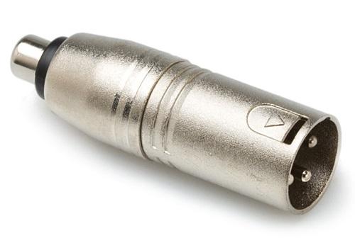
It might be good to mention that I used an single ended connector like shown here: (since the pre-amp involved has an RCA output)
So following your explanation it is apparently correct that I get the Vocm voltage at the OPA's input pins. Is there a way to work around this (without having to introduce a DC-blocking cap)?
Excuse me, it was the same when the XLR cable was disconnected from the pre-amp. And I measured from the XLR connector, (so before the 560 ohm resistor) not directly at the IC pins.
The pre-amp wasn't designed to be able to compensate such a high DC offset so the input signal at the XLR is not exactly at 0V anymore after connecting the XLR cable. ((iirc a few hunderd millivolts)
I talked about de problem with the other engineer today and he didn't understand what the DC that's fed into the output of the pre-amp has to do with the ability to drive a 560 ohm load. Could you elaborate a bit more?