Part Number: OPA335
Hi all,
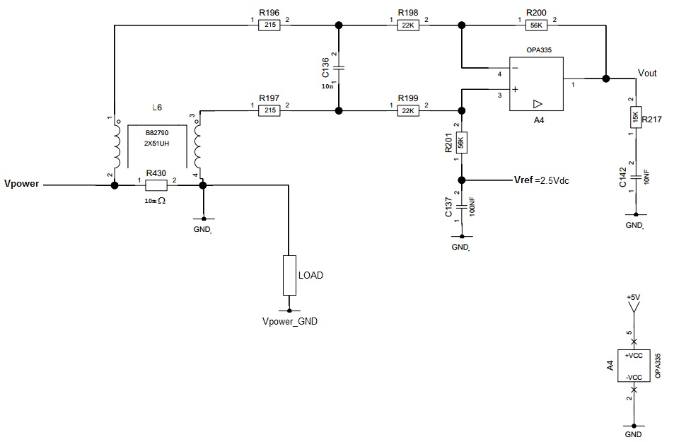
I'm facing an issue in the circuit below: that is a differential current amplifier for sensing current flowing on R430 (sensing resistor). The signal across R430 is filtered with L6 and with an RC low pass filter. The OPA335 is used with a gain of 56/22 = 2.54, and with a voltage reference of 2.5Vdc (that is used because Vpower is and AC voltage). When no current is flowing in R430, Vout=2.5Vdc. OPA335 is supplied with a 5Vdc and GND.
Here is the problem: during power-on or power-off of Vpower, an overvoltage / udervoltage appears on V+ and V- of OPA335 (consider ther LOAD is inductive, so under/over voltage peaks are usual), and consequently I rarely see signal Vout stucked at 1.18Vdc, even when Vpower is not present anymore (I checked voltage across C136 and is 0V). That situation persists until 5V power supply is switched off.
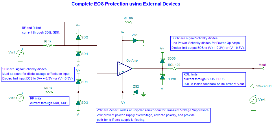
I guess there are some latch up related problems, so I'm looking for a solution to improve the robustness of the circuit. Consider that I can't modify the PCB, so I'd rather prefer to find a pin2pin of OPA335 with some kind of protection of the input pins.
Thanks
Sandro