This thread has been locked.

If you have a related question, please click the "Ask a related question" button in the top right corner. The newly created question will be automatically linked to this question.

INA233: How to drive INA233

Part Number: INA233

Hi all,

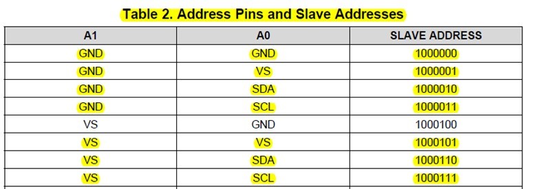
For my applicatoin, there are eight sets INA223 on custom board, the H/W address pins and slave address setting are as below:

I used INA223 for the first time , please give initial , configuration and example code for read bus voltage, current, power, and shunt voltage。

Thanks.

Best Regards.

  • Hi SMART,

    We do not have a sample code for the INA233 but we do have some Linux drivers for other digital output devices. You could use this as a reference. You can find the links in the following website:

    Also, we have a video tutorial that discusses how to  program the digital output current shunt monitors for direct current and power readouts. Find link below:

  • Hi,

    I saw the website and datasheet , i don't know how to use INA233.

    Could you guide INA233 initial and base configuration ?

    I have a project using eight INA233 to monitor custom board power and current.

    That is urgent , please give a support.

    Thanks.

  • SMART,

    We have the INA233EVM available for you to use to learn firsthand how the part works - that may be of some value to you.  Also, there is a FAQ post about the INA233 that explains how the device takes measurements and how to configure the energy/power accumulator, and has a spreadsheet to help you determine the coefficients to use, which may also be of some use to you.

  • Hi,

    For example:
    When the MCU use READ_VIN(88h) by I2C , the data return was 5C 02 or 8C 0D..
    From INA233 datasheet "Full-scale range = 40.96 V (7FFFh) and LSB = 1.25 mV"

    How to calculate the VBUS voltage ?
  • I believe that perhaps the byte order you are showing is reversed - so that the actual hex numbers reported would be 0x025Ch and 0x0D8Ch.

    25Ch = 604, 604 × 1.25mV = 0.755V
    D8Ch = 3468, 3468 × 1.25mV = 4.335V

    Does that correlate with your expectations of the system?
  • Hi Jason,

    question 1 :
    In INA233 datasheet description
    - The last three data bytes are a 24-bit unsigned integer that counts the number of samples of the instantaneous input power that are applied to the accumulator.
    - Total Accumulated Unscaled Power (Accumulator_24) = (rollover_count × 216) + Accumulator
    - Accumulator _ 24 [n] - Accumulator _ 24 [n - 1] / Sample _count [n] - Sample _count [n - 1]

    I use READ_EIN (86h) command, the value return ...
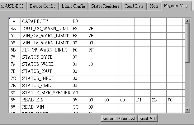
    REG_READ_EIN(86h) = 06 00 00 00 85 C3 03
    Input power = 3C385 (Sample count high byte), but i don't full understand what is the parameter? how to calculate power and watt?

    ===========================
    question 2:

    I use INA233 to read custom board by I2C , the custom board used extern power supply (Input 3.3V / 1.5A).
    The power supply screen display real current value is 0.16 A.

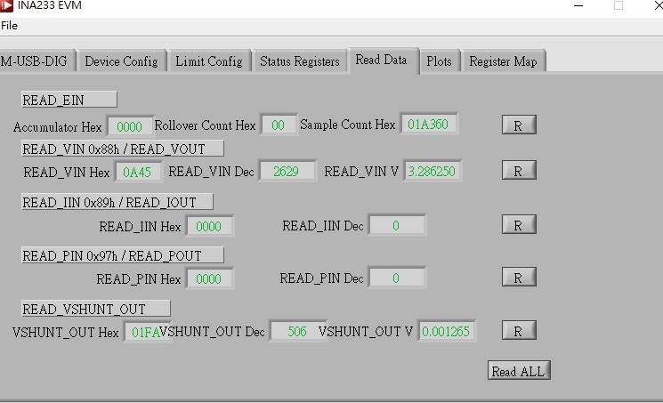
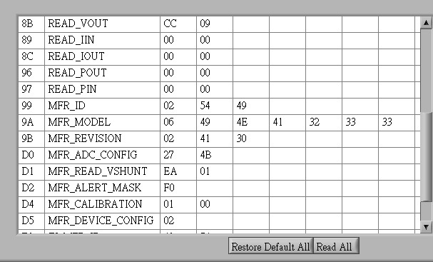
    But read INA233 return READ_IN, READ_IOUT, READ_POUT and READ_PIN are zero.
    What happened? INA233 can read READ_VIN, but cannot read others?

    READ_IN(89h) = 00 00
    READ_IOUT (8C h)= 00 00
    READ_POUT (96 h)= 00 00
    READ_PIN (97 h) = 00 00
  • Hi,

    Could you help my questions?
  • SMART,

    The INA233 has an energy accumulator, which is what you are using when you read EIN.  It is essentially a continuous sum of the value in the power register after each sample.  You can learn more about this feature at https://e2e.ti.com/support/amplifiers/current-shunt-monitors/w/faq/3585.using-the-power-accumulator.

    The device itself is an ADC with a 2-input mux.  One measures the bus voltage (READ_VIN) and the other is the voltage across the shunt (MFR_READ_VSHUNT).  Put values in MFR_CALIBRATION to essentially divide the vshunt value by the shunt resistance to get current, READ_IIN.  Then multiply the current by the bus voltage to get power, READ_PIN.  We're just doing I=V/R, then P=IV.

    Section 8.2 of the data sheet shows an example of how to program up the part for use in a system.

  • Hi,

    i don't full understand, for example as below please guide me more detail. Thanks

  • Hi,
    How to get both value of Ireg and a Current_LSB on my table?
  • SMART,
    There is a short video that discusses this briefly: training.ti.com/getting-started-current-sense-amplifiers-session-15-programming-power-settings

    Register D4, MFR Calibration, is where you set the appropriate hex code to adjust the current_lsb. You can see it defaults to 0x0001, which is a very small value and basically only very large input sense voltages will even move the READ_IIN register at all. Follow the data sheet example in section 8.2 to see how to set up the device for current, power, and energy measurements. In that example, we use a 2mOhm resistor, and we select an appropriate value of 1mA/bit for Current_LSB, and the resulting D4 register value is 0x0A00h. Perhaps you can use that as a starting point, and as you work through the example, adjust it to fit your particular application.