This thread has been locked.

If you have a related question, please click the "Ask a related question" button in the top right corner. The newly created question will be automatically linked to this question.

OPA551: Max Voltage Rating for Vout

Part Number: OPA551

Hi Team,

Quick question on the OPA551. Is there a max voltage rating on the Vo pin?

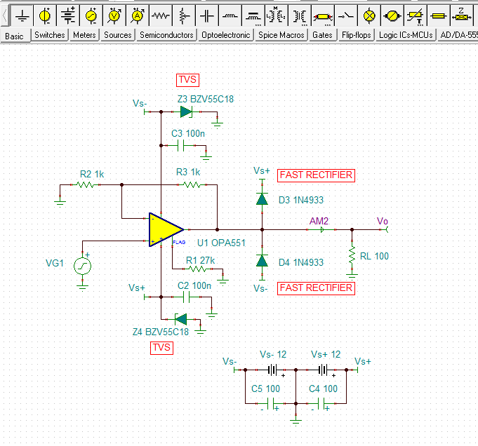
I see that in the Abs Max rating I'm directed to the SoA curve to ensure the device doesn't overheat, but I'm more interested in a transient voltage rating. I have to inject a very large voltage & current to the output (A Lightning Compliance Test) and need to determine what voltage I need to clamp at in order to protect the OPA551. 

My Vs is +/- 12V and looking at the Vout recommended operating conditions it looks like you recommend staying under/above the supply by 2V at 10mA. Therefore I assume I would be safe if I clamped the Vout rail at +/- 10V and limit the current to 10mA max. Is this correct?

Regards,
Hayden

  • Hi Hayden,

    I am looking into your OPA551 questions and will get back to you when I have the answers.

    Regards, Thomas
    Precision Amplifiers Applications Engineering
  • Hello Hayden,

    The OPA551 internal ESD diodes are rated at 10 mA maximum continuous and can't be utilized for surge protection. That kind of protection needs to provided extenal to the OPA551.

    The main consideration regarding the output voltage is to prevent the output pin voltage from exceeding the supply rail voltage. This is normally accomplished by connecting fast, or ultra-fast recifier diodes from the output pin back to each supply rail as shown in the diagram below. The diodes must be selected to handle the surge current and also remain off during normal operation. I show the IN4933 fast rectifier, but there are others such as the ES1A and RS1A that could be used.

    Then, at each OPA551 supply pin, there needs to be a power supply bypass capacitor that exhibits the least impedance at frequencies associated with the surge event. I show a 100 nF and that may be about right. These capacitors need to be located as close to the device power supply pins as possible and exhibit very low series inductance to ground. The capacitors appear as a momentary low impedance path to ground, to a transient voltage change.

    Directly parallel to a bypass capacitor a transient voltage suppressor (TVS) is required. Should an output rectifier diode turn on, the TVS provides a path to ground for the surge current.

    The supply line diodes shown in the schematic are actually zeners, but TVS diode should be used instead. The TVS diodes have faster response times then zeners and are designed to handle repetitive current surges. Their standoff voltage needs to be higher than the operating supply voltage. Since you are planning on 12 V supplies, an 18 V TVS should be about right.

    Regards, Thomas

    Precision Amplifiers Applications Engineering

  • Hi Thomas,

    Thanks for the detailed response! Extremely helpful. We've implemented your suggestions and will continue with the lightning testing.

    Regards,
    Hayden
  • Hi Hayden,

    My pleasure to assist.

    Regards, Thomas

    Precision Amplifiers Applications Engineering