This thread has been locked.

If you have a related question, please click the "Ask a related question" button in the top right corner. The newly created question will be automatically linked to this question.

mV signal to v isolator

Other Parts Discussed in Thread: LMC662, LMC6081, TLV9002, TLV9062, OPA2170, OPA2172, TLV2170, TLV2172

hi Everyone

I am new to  electronics

I wanna to use a sensor having mV output which is not suitable for arduino

i have found that this can be done with non inverting operational amplifiers 

Can you please guide me how can i do this 

what components should i use

Sensor   MG812

Load   100mA

Thanks in advance

  • Hi Harjot,

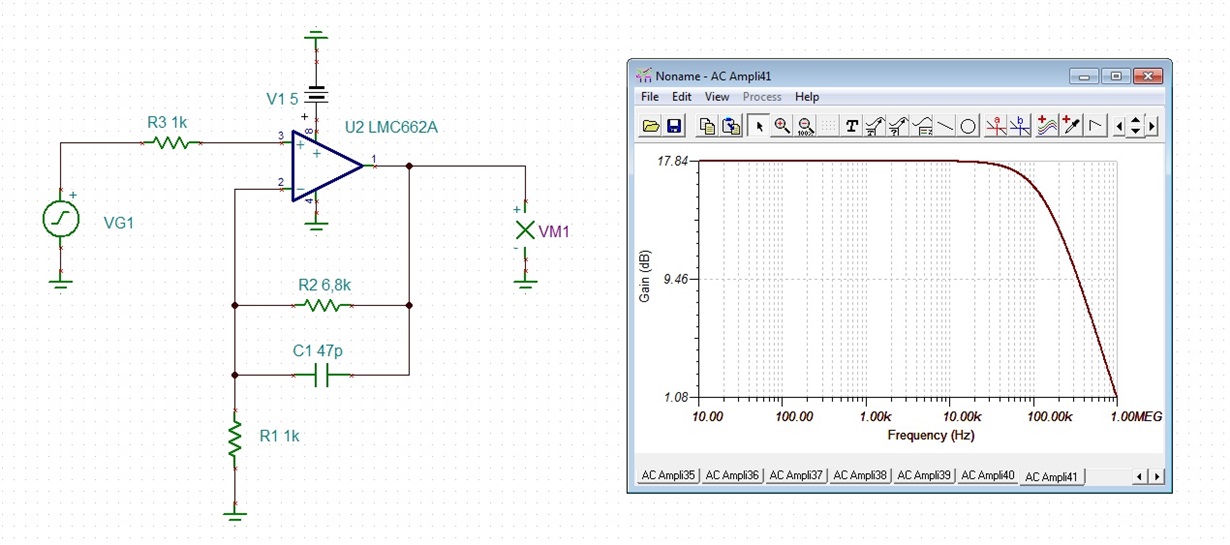
    usually, the LMC662 is used for this purpose because of it's extremely low input bias current and low cost. This circuit could be used:

    Because the zero emf of sensor is up to 500mV, only a gain of 7.8 is used. R3 protects the input. Feedback resistances R1 and R2 are kept low to keep the OPAmp stable. C1 provides a phase lead compensation to further stabilize the OPAmp.

    Take care: This circuit is still producing rather high noise and has problems driving capacitive loads. This has to do with the LMC662 which does not like capacitive loads. So, it would be wise to add a passive low pass filter and a buffer. What do you want to drive with this circuit? An ADC input? Or a cable?

    Kai

  • Hi Hojart,

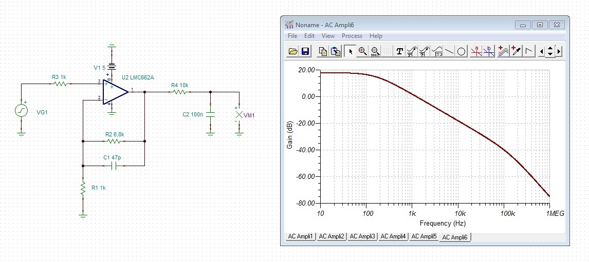
    if you have an Arduino with ATMEGA328 and want to directly drive the ADC input, you could use the following circuit:

    Corner frequency of low pass filtering is about 150Hz. If you need an OPAmp with lower input offset voltage, take the LMC6081.

    Kai

  • Hello,

    Here's a link to a good design guide for non-inverting amplifier circuits.  The LMC662 is a good amp but there are much newer alternatives which perform better for lower costs.

    For +1.8V - 5.5V supplies look at the TLV9002 (1MHz) or TLV9062 (10MHz).

    For +4.5V - 36V supplies look at the TLV2170 (1MHz) or TLV2172 (10MHz).  The OPA2170 and OPA2172 are higher performance versions of the TLV devices.

  • thanks everyone
    can anyone please explain me physical connections of circuit??
  • Hi Harjot,

    according to the datasheet of MG-812 pin1 and pin3 are for the heating. So, connect pin1 to +5V and pin3 to GND. Datasheet is not clear how to connect pin2 and pin4. Probably, pin2 is also connected to GND and pin4 is the output of sensor. If VG1 in my simulation is the sensor output, then connect the lower end of VG1, which is signal ground to pin2 and connect the upper end of VG1, which is the output of sensor to pin4.

    VM1 is the input of your arduino board (ATMEGA328).

    Datasheet of MG811, which is very similar to MG812, states:

    "In sensor testing, the impedance of amplifier should be within 100-1000GΩ, its testing current should be control below
    1pA."

    This means, that the input bias current of OPAmp should be ultra low. For the LMC662 and LMC6081 the input bias current is guaranteed under 4pA.

    Kai
  • Thanks Kai!

    Agreed that with the MG812's 1pA input bias current requirement the op amp choices I previously recommended don't have low enough Ib to work. The two options you've recommended are great!