


Dear,
I am beginning my way with LPV821. I have a sensor with 5 wires. Two of them form a NTC thermsistor. I can calculate the temp from them :) That is nice.
The other two, theoretically, polarize themselves when measuring and between anode and cathode they present a voltage drop ~ 60 mV.
The last wire is the shield. Well, it is not a wire, I just separate and twist the shield so it does not mess with the other wires.
I have wired a LPV821 in differential amplifier configuration as in the following diagram.
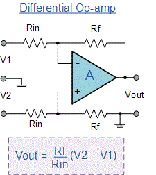
In my case, Rf is about 47 kΩ and Rin around 1 kΩ, so the amplifier gain is about 50. For a 30 mV input signal, Vout is around1500 mV = 1.5V.
To test this, I feed to V1 and V2 a voltage divider measuring around 20 mV. This helps me testing the input range. I do not have the sensor inputs connected at this step.
The amplifier works, the signal is amplified and I can read the ADC in my msp430.
Unfortunately, when I replace such testing voltage divider and input instead the two wires of the sensor, my output is zero. However, I can read around ~30 mV when directly measuring them with my multimeter!
So, probably I am understanding (and doing) something wrong. Please give me your opinions! My thoughts are:
- Maybe I need to connect the shield to my circuit GND? I am not doing this. And because of the multimeter works, I do not thought was necessary.
- Maybe the sensor output behaves in a way the LPV821 cannot follow it?
Well, I do not know! Please share your knowledge because my opamp skills are quite lame :)
Have a nice weekend!


