This thread has been locked.

If you have a related question, please click the "Ask a related question" button in the top right corner. The newly created question will be automatically linked to this question.

THS4541: THS4541 as ADC driver: induces DC offset on the input signal

Part Number: THS4541
Other Parts Discussed in Thread: ADS41B49,

Hi,

I am currently testing a THS4541 to drive the input of the ADS41B49 ADC.

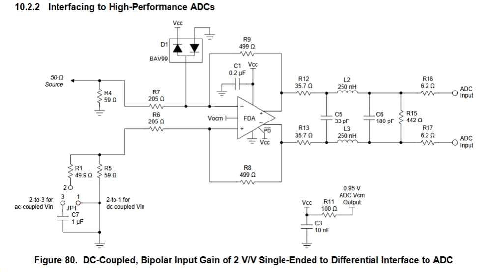
The input is DC coupled and I am using the recommended circuit specified in the THS4541 datasheet (Figure 80, page 47)

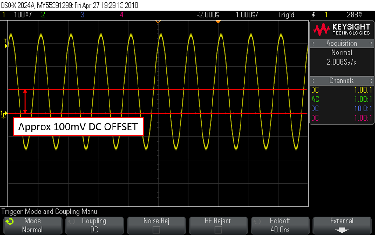
The issue I am having is that when I connect anything at the input, the THS4541 "pulls up" the signal a couple of hundreds mV. For instance when I apply a Sinewave of +-500mV reference to zero, the reference changes to approx 150mV. IT gets back to zero when I disconnect it. Is this behavior expected? Any pointer of what could causing it? The Protection diode perhaps?

The only difference I see between the circuit in the datasheet and my implementation is that the ADS41B49 has a1.7V Vocm instead of a 0.95V. Could that be the cause?

Thanks in advance for your help

  • Hi Javcel,

    what do you mean by "the reference changes to 150mV"?

    Kai
  • Hi Kai,

    Thanks for your answer.


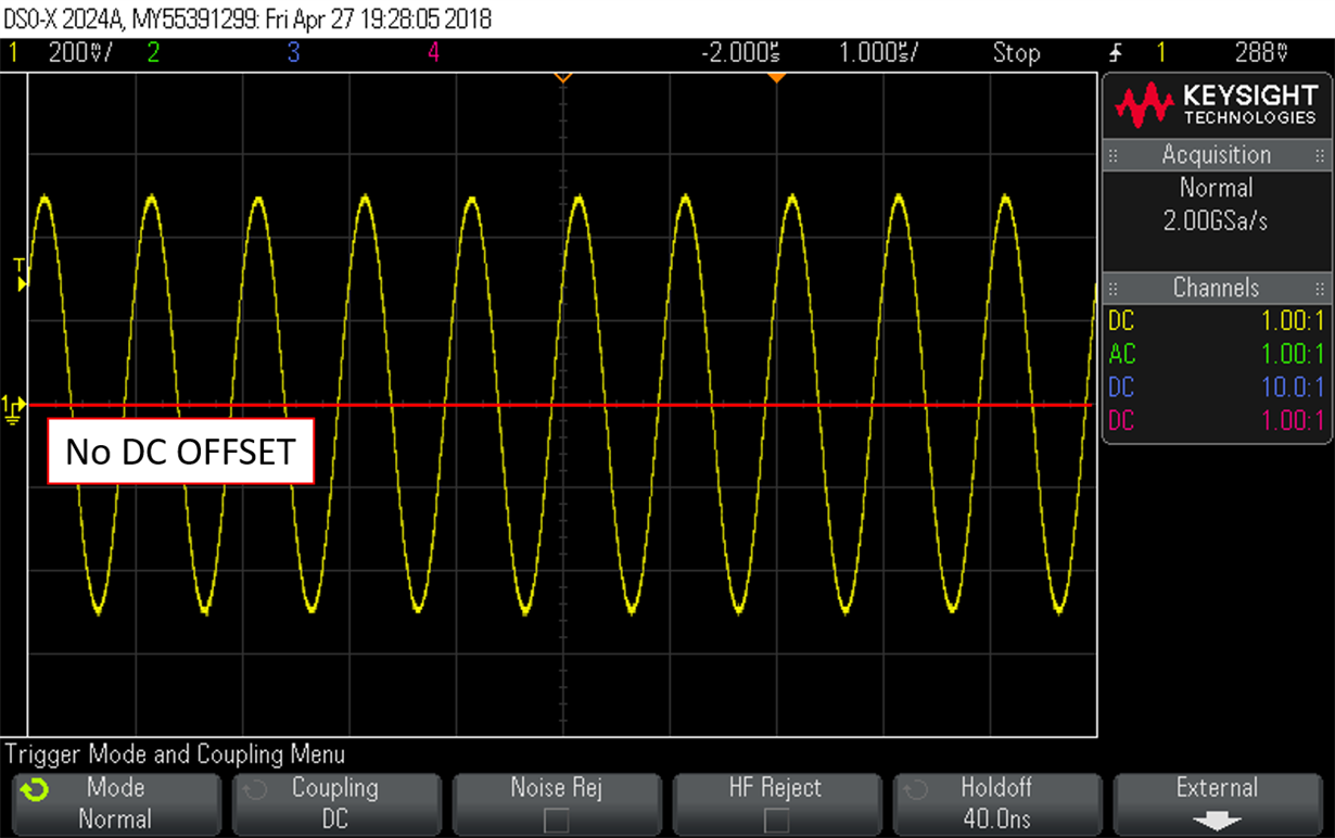
    Sorry, I was not clear enough. What I mean is that the sine is nt over zero anymore but it has a DC offset of 150mV.

    Edit:


    A couple of images to clarify:

    Output of a Waveform generator connected directly to the Oscilloscope:

    Output of a Waveform generator connected to the Oscilloscope and to the THS4541 with a "Tee junction":

    Kind regards,

  • Hi Javcel,

    Can you confirm whether the waveform generator you are using is AC coupled or DC coupled? I think it is possible that the shift in DC voltage is due to the waveform generator being AC coupled. If the waveform generator cannot support DC voltage output then it is probably good to assume that the generator is AC coupled. If yes, then you need to short across 2-to-3 on jumper JP1 for ac coupled Vin.

    If the generator is DC coupled, then you need to short across 2-to-1 on jumper JP1 for dc coupled Vin.

    Best Regards,
    Rohit
  • Hi Javcel,

    this has to do with the Vocm. The output signal is referenced to the Vocm potential. And because the OPAmp is supplied with a single supply and R4 and R5 are forced to GND with their lower ends, the Vocm potential is dividing down to 0V when going from the right to left in the circuit. Finally, at the 50R source impedance of wave form generator a DC voltage develops which seems to shift up the sine.

    Kai
  • Thanks for the answers. I can see now why is this offset happening. In principle, there should be no offset seen by the ADC. We are still working on the software implementation to be able to evaluate it properly.

    Thanks again