This thread has been locked.

If you have a related question, please click the "Ask a related question" button in the top right corner. The newly created question will be automatically linked to this question.

INA223: Gain VS Frequency

Part Number: INA223

Hi Sir


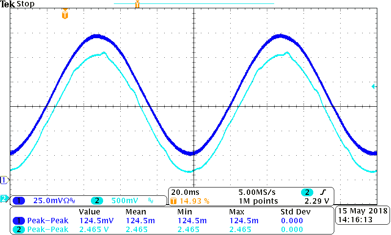
I am trying to check Figure 20 (Gain VS. Frequency) in datasheet. 

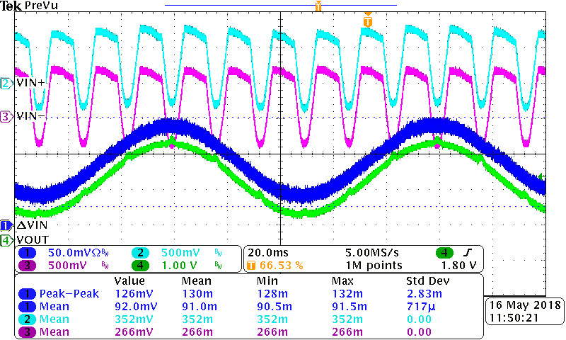
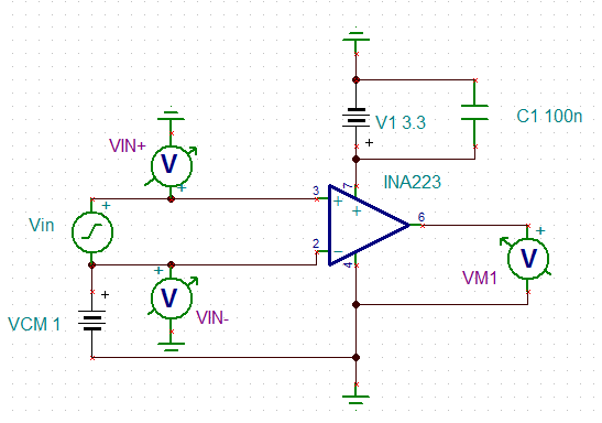
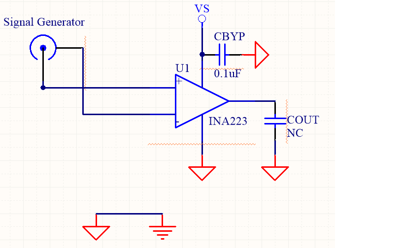
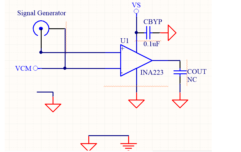
For simply measurement, the stimulus is from the functional generator (AFG3102) which is floating signal source; I connect the signal output across the VIN+ and VIN- directly.


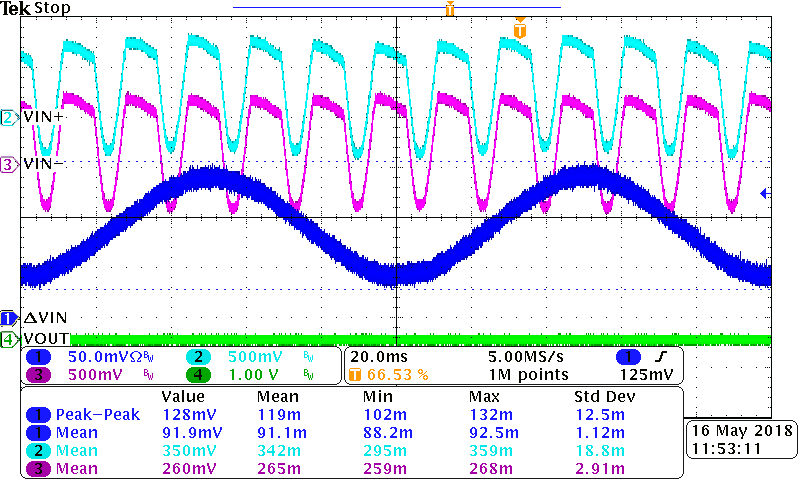
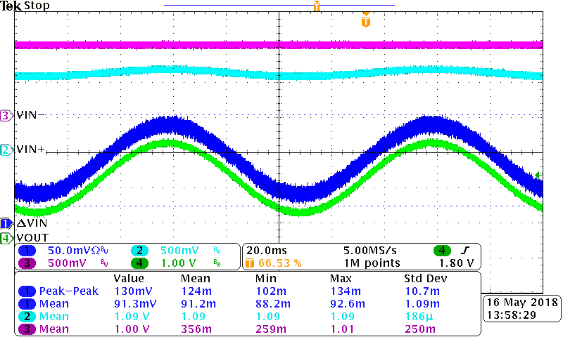
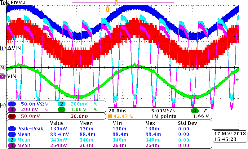
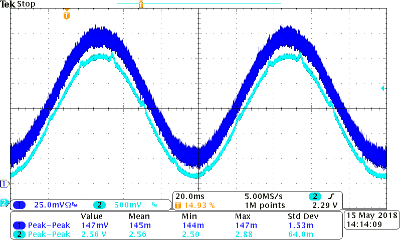
But found the interference on output waveform, for removing other out of band noise, I use the “Average” function supported by oscilloscope, the interference is still observed


Should I miss something essential to carefully take into account?


Thanks

Regard

Ben


  • Hi Ben,

    to let the inputs float referring to the GND pin is no good idea. Have you ensured that the common mode input voltage is within the range 0...26V? The input voltages must not become negative referring to the GND pin.

    Try to emulate a typical application with a shunt, a load and a bus voltage like shown in datasheet.

    Kai

  • Hey Ben,

    If you wish to confirm the datasheet specifications for gain vs. frequency, then you will need to run them as specified. So place a 10pF capacitor on the output pin, add a common-mode, and reduce your input signal from 125mVpp to 100mV.

    To add a common-mode, connect the VIN- pin (the low side of function generator) to anywhere between 0V and 26V. Figure 20 was done with common-mode = 1V as seen at top of page in the datasheet. The point is the system ground of the function generator can drift from the system ground of your INA223 circuit and possibly create a ground loop current.

    Please run the test as described and see if the harmonic nose remains. This noise looks to be 60Hz noise. Ensure that you do not have any noise coupling into your circuit from a power supply. What could help is shielding your entire circuit with a metal enclosure and connecting this metal box to system ground. Also, make sure the INA223 has a decoupling capacitor very close to the VS and GND pins and that your cables are as short as possible.

    Sincerely,
    Peter Iliya
  • Hi Peter

    Thanks for amazing identification to my issue and helpful recommendation

    After checking waveforms, the 60Hz is from signal generator

    Do you have any idea to the waveform? (every channel is labelled)

    (1) INA223 is in shunt voltage mode Gain = 20V/V

    (2) INA223 is off

    (3) Additional common mode applied

    My setting is as follows

    Power supply: floating output (where VS = 3.3V)

    Signal generator: floating output

    ΔV : Differential Probing

    V+, V- and Output: Single ended probing with respect to system GND.

    Another question raised for Gain = 300V/V, since the minimum allowable ΔV = 20mV

    I try to attenuate simply but it is very noisy

    And even cannot find the small stimulus after connect across VIN+ and VIN-

    Appreciate commenting

    Regards

    Ben

  • Hi Ben,

    can you give us a schematic which shows how you have connected the common mode voltage to the inputs?

    Take care, even if the signal genrator output is said to be floating there's always a certain coupling to mains voltage via stray capacitance. That's very probably the reason why the 60Hz appears in your measurements.

    Kai
  • Hey Ben,

    I am not sure why your power supply and signal generator are floating. Every instrument and device needs to have a common ground, specifically Earth ground. See the schematic below.

    Best,

    Peter Iliya

  • Sir

    Sorry for making you misunderstood!

    Many instruments in my lab are “floating type”, which one end of output terminal is not fixed tied to earth GND

    Measurement is made by the following illustration below

    (1) Linearity and accuracy

    ΔV is developed across RSENSE by constant current flowing through

    (2) Gain VS Frequency

    2.1 Initially

    Set frequency, amplitude and offset of the signal

    While IN+ and IN- is falling to below 0 (out of common mode range), the output waveform looks weird at that moment.

    The 60 Hz is seem to be intrinsic and be amplitude modulated

    CHannel M = IN+ - IN-

    2.2 Corrective

    Additional VCM applied to IN- with respect to GND

    The next challenge is to check the Gain = 300 V/V.

    Could you please help to guide me as usual?

    I have problem in attenuating the signal.

    The signal generator can only set 20mV minimal swing

    Thanks

    Regards

    Ben

  • Hi Ben,

    as Peter and me are repeating over and over again: It's not allowed to let the inputs float!!!!! A 18µA input bias current is flowing out of the input pins Vin- and Vin+ and must flow back to the GND pin of INA223. This will work if a shunt and a load is connected as shown in the datasheet. So, only the first schematic of your last post shows a circuit the INA223 is designed to work with. The second schematic will not work and the according measurement makes no sense at all. The last schematic can work, if carried out carefully, if the INA223 sees exactly the same situation as in a standard application with shunt and load.

    Don't think that a floating type instrument is really floating. The signal ground of such a lab is usually connected to protection earth via hybrid grounding (1...100nF between signal ground and protection earth). And there exists almost always a stray capacitance between phase line of mains voltage and signal ground caused by the interwinding stray capacitance of mains transformer or transformer of AC/DC switcher supply (200pF...10nF). These two capacitances form a capacitive voltage divider between phase of mains voltage and protection earth and make the "floating type" instrument output emitting a strong and distorted 60Hz sine of several volts at its signal ground terminal. This 60Hz noise is what you measure all the time. This noise only dissapears when you connect the signal ground of instrument to the signal ground of IN223 circuitry.

    Kai

  • Hey Ben,

    Your signal generator needs to be grounded as Kai is saying. The reason the 60Hz noise goes away in your second scope shot is because you are providing an analaog ground to the function generator (which counts as "grounding").

    A 20mV swing is pretty good, but for the gain of 300V/V you will want a input voltage closer to 3mV peak-to-peak. This will provide just below a 1Vpp output swing. You need to ensure this because the gain vs frequency tests are small-signal tests that do not consider slew-rate or output drive capabilities of the part. Usually we create these small signals with an external attenuator or use frequency response analyzers, such as the Bode 100.

    Best,
    Peter Iliya
    Current Sensing Applications - TI
  • Sir


    Thank you all pay so much attention to my case!

    Have you ever made a correlation between the time domain waveform and the frequency domain curve?

    What if the input or the output signal is distorted (not monotonic / modulated or any disturbance), can I still simply check the ratio of output and input (RMS or P-P)?


    Regards
    Ben
  • Hi Ben,

    when you test an application you usually take a sine of variable frequency to measure the frequency response and eventually the distortion. You can additionally test it with a square wave. This will show you how the settling performance is in terms of settling time overshoot, etc. This can also give you much information about the stability of your application. Much of this data is given in datasheet: You have the offset errors, the frequency response, the input step response and also the linearity. Nonlinearity error of INA223 is specified in datasheet with +/-0.01%. This is a very little nonlinearity which allows you to detect shunt voltages and bus voltages of nearly any waveform without generating additional errors.

    Kai