- Ask a related questionWhat is a related question?A related question is a question created from another question. When the related question is created, it will be automatically linked to the original question.
Original question:

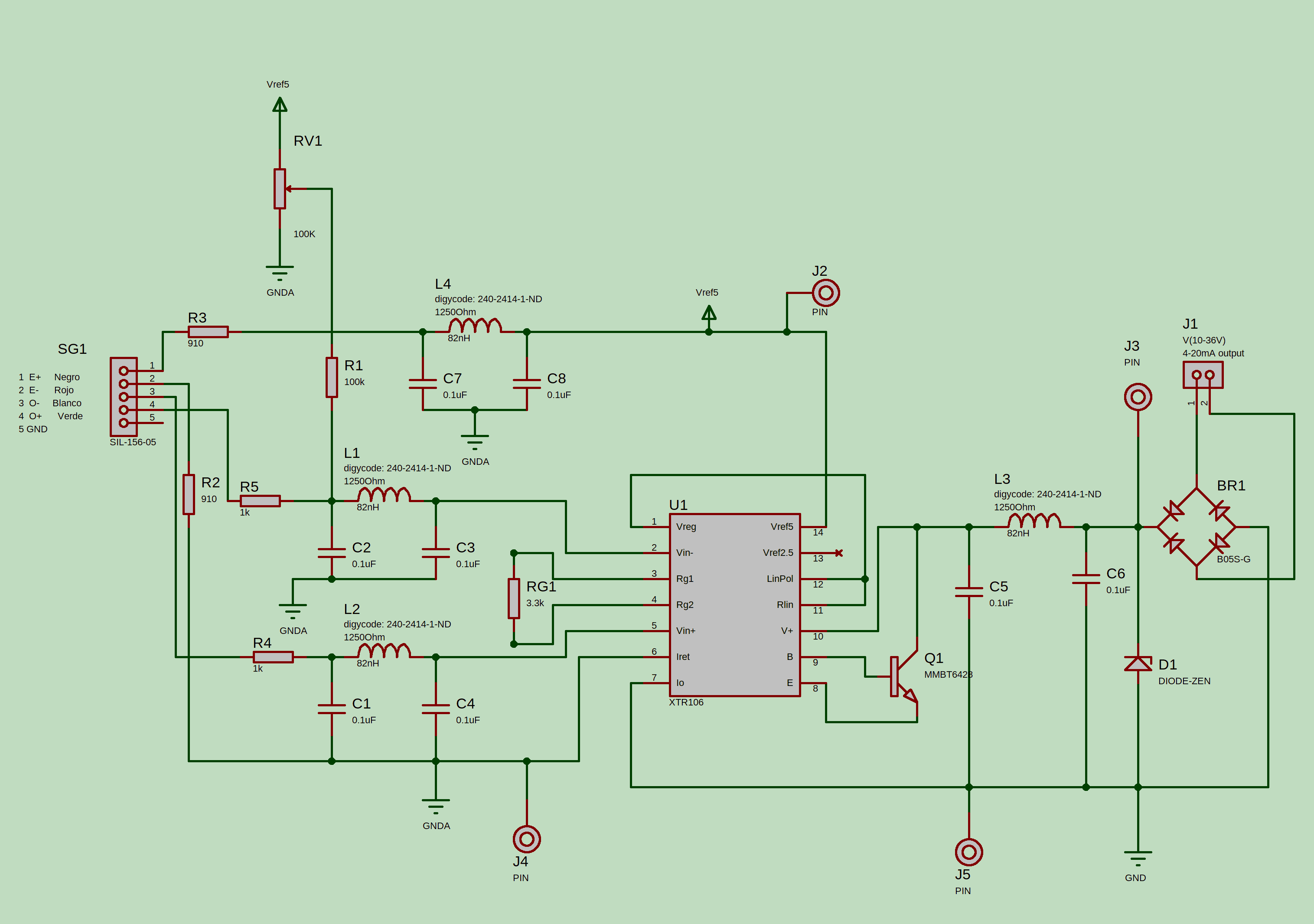
XTR106: Design a 4-20mA transmitter for a 700 Ohm input impedance Load Cell
Hi,
I've designed a 4-20mA transmitter with a xtr106 for a load cell. The problem is that i'm getting arround 13mA with no bridge connected, and when i connect it i get arround 2mA more. With the design, 2mA is the current across the bridge. As i understood from datasheet, the idea is that al comsumption refered to Iret would not appear in the outpu, just the produced by the difference from Vin+ and Vin- of the xtr106, am i correct in this assumption? So i don't know where those 13mA come from.
Any help would be appreciated, y attach the schematics.
Thanks in advace.
Pd: i'm using a Fluke 709 precision loop calibrator for the measurements.