A related question is a question created from another question. When the related question is created, it will be automatically linked to the original question.
If you have a related question, please click the "Ask a related question" button in the top right corner. The newly created question will be automatically linked to this question.
I solved this issue in a project I did in school many years ago. I had two input sensors looking in two slightly different directions and used automatic gain control (LED, straw, and photoresistor) to make the sum of the signals a constant level so that the difference of the signals was a properly scaled direction error measurement.
My careabout was angular error regardless of input amplitude. What is your care about? In other words, what characteristic of the input signal matters most? How fast does the amplitude change and what is the input (maximum) frequency? This is important to choose components for AGC.
The input amplitude is control manually, the speed is not important. The important part is the output amplitude. Could you also recommend other Op-Amp beside uA741?
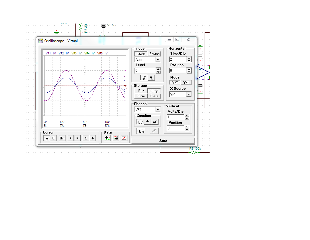
Please see attached. With the circuit I design and simulated, I expected to see output amplitude 0-3V sine wave at VF4 node when the input is in the range 0-2V sine wave. However the result is as attached. Is there a limitation with the LM13700?
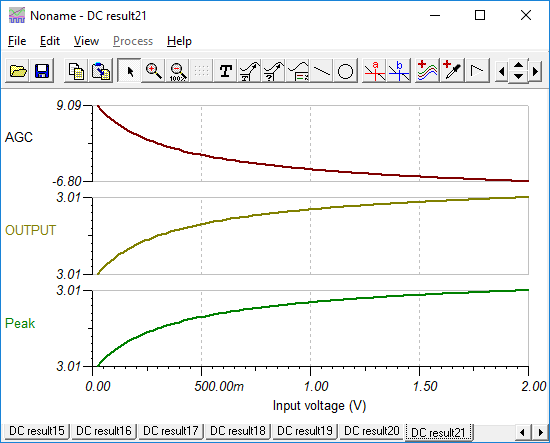
I spent some time tweaking the circuit. Major changes were to add a 2nd gain stage for more dynamic gain control. Bump supplies up to +/-15V. Replace LM137000 pin 7,8 buffer that shift output voltage by roughly -1.4V with an unity gain op amp buffer. I added a peak detector reset, just in case it is needed.The circuit now takes an input of +22mV to +2V DC and amplifies with automatically control gain to get +3V DC output.
I'll let you test and modify if needed to process an AC input signal. Things to watch are the bleed time of the peak detector (R9), response time and stability of the servo amplifier.
Quick update. I saw AC signal distortion so I moved the peak detect input to the buffered output to fix that. I notice that the circuit is very touchy for DC shifts over gain and with potentiometer adjustment. Therefore I suggest adding AC coupling based on the lowest frequency input you expect. It also was not stable with the AGC output ; I lowered AGC servo gain and it seems to stabilize OK now. How it responds to changing input is not tested however. This version is a step in the right direction, but probably needs more work and certainly more testing.